So, again I am hoping I am not missing something cause I did look around a bit and it does not seem obvious.
but.
Frsky xsr or x8r, if I want sbus I use the number 4 quadrature input on pin 4 for signal right? ( cant find the place I saw that before mentioned with a picture)
how about basic PWM input?
for the GPS I need to hook a volt meter to the signal wire and make sure it is 3.3 right?
As written here: https://github.com/mirkix/ardupilotblue
The RC receiver signal has to be connected to connector E4 pin 4 of the BeagleBone Blue. This pin is a multi protocol pin (S.BUS, PPM-Sum, Spektrum Satellit DSM), the protocol will be automatically detected.
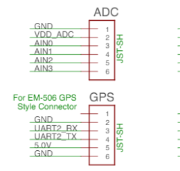
If you connect GPS to the GPS port(showned on the diagramm of the above link) it is providing 5 Volts on pin 5 on the JST connector, @mirkix is warning about exceeding voltage,please make sure the GPS does not exceed 3.3 volts
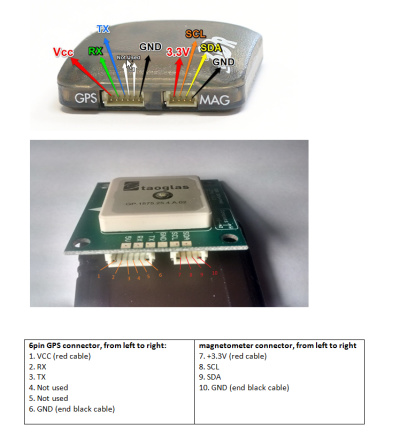
So if I got a Ublox 7m that was working fine with an apm2.6 would that be a direct pin to pin connection to the gps port without worrying about voltages? I found a few pinouts images but nothing that shows voltages…
Also is there a standard for the way the pin numbers are, for example E4 pin 4 that is the pin that is closest to the center of the board for that port right? is there a full diagram of this board and a simplified one ( other then the super simple port labeling one that is everywhere)?
Pin 1 is on right hand side when you place the board so the USB is on left and battery connector on top. But make sure that you get the right pinout using a voltmeter and confirm reading the 5Volts on pin 5.
If the GPS TX data output more than 3.3 volts, you can make a voltage divider using 2 resistors and divide the output to get the good ratio. You can solder these resistors inline in the cable using heatshrink.
Ok, powered up gps from blue without tx and rx connected and the signal on the tx line from the gps is 4.5 ish, So how does this 2 resistor setup work? what type of resistors do i need, then i just wire them inline on the tx wire right? tx to rx, rx to tx?
Ok
So its the basic 1/3-2/3 divider
Take the TX signal connect to 1k resistor
Other side of resistor goes to BlueRX and to a 2k resistor
Other side of 2k resistor goes to ground