Please note the reason why I dedicated a TFMINI as RangeFinder on I2C is because the POC generates a LOT of traffic and sometimes it affects the Telemetry channels. There a now method to alleviate this by keeping traffic local.
1 Like
thank you very much sir, this is great
it worked. highly appreciate the help
Hello @ppoirier,
I have 5 TFMINI here in Serial mode and i read practically every single post where you talk about the POC and all the implementation and feedbacks from other users but i am a bit lost.
Can the TFMINI be reconfigured to work in I2C so that i could attach them directly to my I2C port on the carrier board ? if yes could you you guide me a bit because i am a bit stuck !
thanks
So here is how to get the TF Mini Plus working on Pixhawk I2C.
Connect your TF Mini via the supplied cables to a TTL to USB adapter.
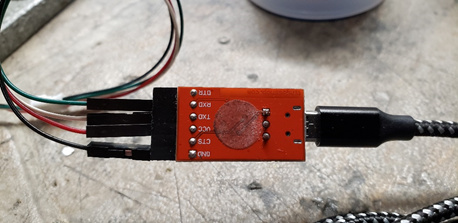
Connect via the USB cable to your PC.
If you have not already downloaded the TFMini Gui…do so from http://en.benewake.com/support
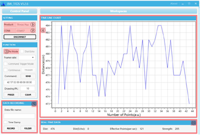
Open the Gui
- Set the product type to TFMini Plus
- Select the correct Com Port
- Click connect.
You should start seeing distance information on the graph in the gui.
Using the command line function issue the following two commands by pasting each in the command line and pressing send
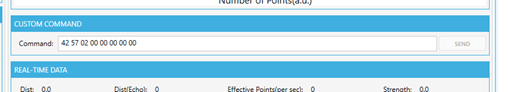
5A 05 0A 01 6A
5A 04 11 6F
The first sets the device to I2C and the second forces a save.
Nothing should appear on the graph from this point on.
Next you need to connect it to your Pixhawk or I2C hub.
Please note that the pinout on the supplied connector has the SCL and SDA reversed. You need to pull out the pins and swap them.
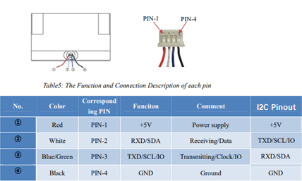
Please note the SCL and SDA are reversed.
You need to configure a few settings in Arducopter.
RNGFND1_ADDR,16 This is the I2C address for the Lidar
RNGFND1_GNDCLEAR,34 This the distance from the Lidar to the ground…easiest way to set it is to have the drone report the distance to the ground when sitting on your workbench and then enter that distance.
RNGFND1_MAX_CM,600 Set this as the max distance the device will be used.
RNGFND1_MIN_CM,30 This is the minimum distance for the lidar.
RNGFND1_ORIENT,25 This is telling Arducopter that the lidar is pointing down
RNGFND1_TYPE,25 This sets the lidar type to TFMini I2C
It should be working now.
Good luck
3 Likes
thank you very much for your prompt answer.
however i do not seem to have a TF Mini Plus !
As soon as i send the command 5A 05 0A 01 6A it says “Wrong Command, please check !”
However on the back of the PCB i clearly see “TF Mini V1.8”.
I have been tinkering with this the whole day unsuccessfully !
thanks again
@rickyg32 thank you for your feedback…i had to dig a bit into it but what you suggested worked and the issue was on my side. the commands have to be sent in HEX in order to work.
I was able to change the address of my 4 TF MINI S on I2C and attached to my I2C port on my carrier board and can see them (they are working). I even tested them while flying and they are preventing the drone to crash (with a bit of delay though). I tried going straight into a big bush and at some point it stopped and did not let me go further even if my pitch stick was full up (which is awesome).
However i noticed a strange behavior in the quadcopter when landing/disarming and the moment i take off.
The system hardly disarms (i have to keep the stick in the disarm position for a while before it actually disarms) and motors have some small burst of throttle randomly. Secondly it is a bit unstable (it’s shaky and lean into one direction on either roll/pitch). I am sure that this is due to some interference on the TFmini but do you have thoughts on what to change in the parameters to make it smoother ?
thanks for your answer.
1 Like
You can enable/disable avoidance using a rc channel so it dont interfere during takeoff and landing
Thanks for the support ! all works now much better !
I got one last thing that i am not able to do…terrain following/surface tracking using the downfacing TF02
something like in this tutorial https://ardupilot.org/copter/docs/terrain-following-manual-modes.html#terrain-following-manual-modes.
It does not seem to follow the shape of the terrain at all but keep a straight line movement without adjusting altitude.
do you have suggestion on that matter ? thanks
Hello sir, i have 2 or 3 lidar lite using i2c port
but if i connected all, just 1 lidar lite can reading in arducopter, any idea for that ?
Please open a new thread with details of the configuration and sensors used
Thanks for the Code Example.
It has served me as a base for my project.
We have connected 8 Sonic and 8 Lidar Sensors via I2C (through a multiplexer)
and sending the the mavlink distance message via serial.
I could not find the library you used to send the mavlink messages, or the ones i found would not compile.
i have used this library and GitHub - mavlink/c_library_v2: Official reference C / C++ library for the v2 protocol
I Hope someone finds this usefull:
1 Like
Is this method going to work with 360lidar???..I’m evaluating to use a ld06 lidar to connect arduino mega through serial port then send distance_sensor data to pixhawk over another serial port.
Hello
This system is is using the rangefinder driver you can use it but you would be limited to the number of sectors.
You need to work with the 360 lidar drivers-proximity driver- for having full sectors coverage
Thank you for your replay @ppoirier,
As you said to use 360 lidar drivers or proximity drivers, so the drivers going to work without modify it?? If yes please provide the link where I can find those drivers.
No, each devices need their own drivers, you may use an arduino to extract information from the rotating lidar and output the Mavlink Proximity message.
As usual, Wiki is your friend
https://ardupilot.org/copter/docs/common-rangefinder-landingpage.html
Hi, thankyou for making such an amazing blog. I had some issues while testing the code…
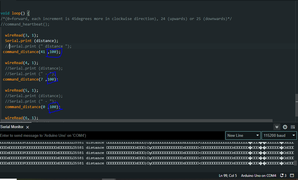
Issue 1: I didnt had the tf-mini sensor so to just test I modified the distance as shown in the image.
I have set the parameters as you have said in mission planner.
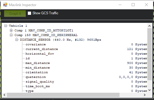
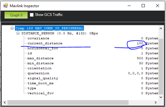
I am getting distance in mavlink inspector correctly as shown in the image below
But when i open the proximity UI it do not show anything as shown in image below.
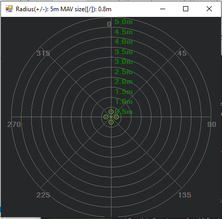
please help me with this.
Issue-2: In my mission planner Prx_type, which prx should I choose?
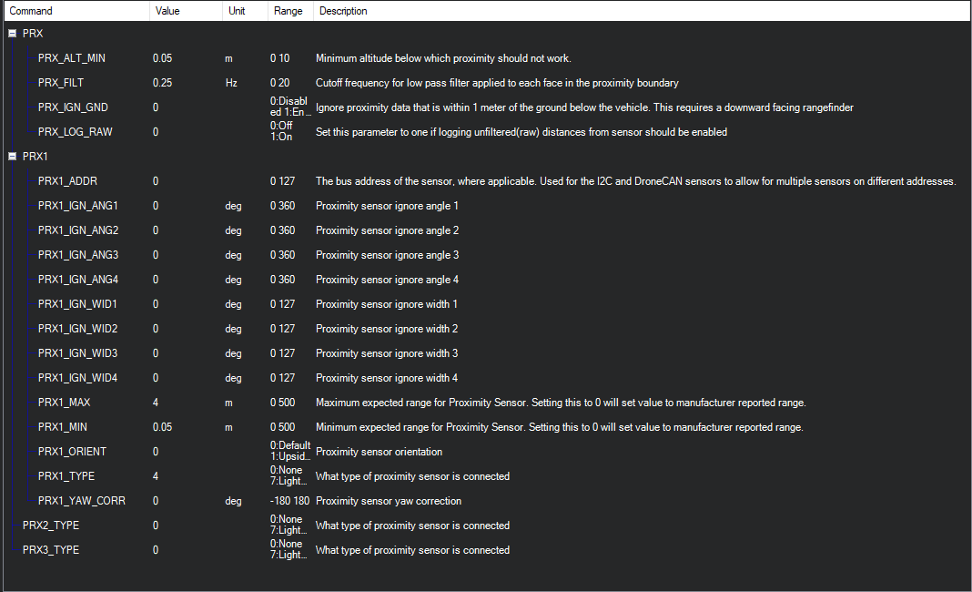
Set it to mavlink proximity type.
1 Like
Thanks for the suggestion. It used to show bad proximity, now that error is gone but the UI does not show any detection.
is your distance sensor updating? it says in mavlink inspector it should say how many HZ its updating at.
Set your PRX1 min max to 0, its already set by the sensor.
1 Like
yes it is updating between 480-523hz and prx min max is already set to 0