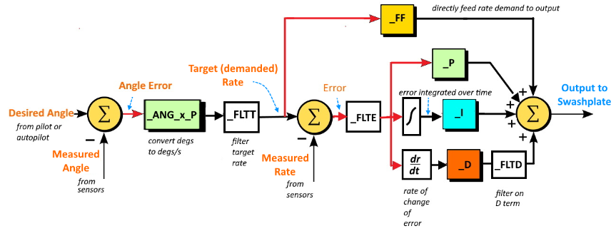
This is from the section for helicopters - within the ArduCopter wiki. (note output to swashplate)
Does this diagram apply to multi-copters? Would there be other changes other than the output going to the motors rather than the swashplate?
I’ve seen other more detailed and complex diagrams of this process - too complex to help me advance my understanding of this topic.
This diagram shows where the _FLTT, _FLTE and _FLTD parameters fit into the process - I’ve always wondered about that.
The current multi-copter tuning wiki was announced by @Leonardthall a year or two ago - but it doesn’t contain this level of detail. If this information is applicable, it would be helpful to multi-copter users to know about it.
The wiki pull request that Fabian did contains more up-to-date diagrams.
And there is a simulink model of the multicopter ATC on the ArduPilot source code.
ATC_RAT_PIT_IMAX
ATC_RAT_PIT_PDMX (only in master)
ATC_RAT_RLL_IMAX
ATC_RAT_RLL_PDMX (only in master)
ATC_RAT_YAW_IMAX
ATC_RAT_YAW_PDMX (only in master)
I’m starting from such a position of ignorance that it’s hard to ask questions where I don’t feel like I’m wasting someone’s time. If there are resources I can study that would help me make more intelligent queries, I’d appreciate the suggestions.
I see that the PDMX parameters aren’t in the parameter wiki - so I guess they will show up in future releases. (I’m sorry - I don’t know what “only in master” means.)
As I understand the description of the IMAX parameters, it sets a limit on how high the Integral gain can go. Is this how high AutoTune can set it? I thought that once the PID gains were set, they were static unless doing an AutoTune.
It controls how high the integration can go. The Integral gain is the multiplier on the integral.
You may benefit from reading up on general PID controllers, or having a look on youtube. It may help to clear up some corners of your understanding.
Master is the code we are currently working on but have not released yet.
When tuning your aircraft you should focus on following the tuning guide. Your understanding will grow over time but the practical process of tuning will probably help you focus on the most relevant parameters.