I am setting up wheel encoders on my mower’s motors. I’ve installed CUI quadrature encoders programmed for 400PPR. The geartrain is 18:1 and so I’ve set PPR to 7200 to start. With power applied to the encoders, I get the expected transitions; 5v squarewaves on A and B with 50% overlap and lead/lag changes with direction verified on the Futaba connectors at the Pixhawk on Aux pins 3-6. Pic here. I have configured the Pixhawk settings per the Wiki.
When looking that the MAVLink Inspector, I do not have a WHEEL_DISTANCE node present.
With RPM 0 and 1 configured in MP Quick tab the RPM remains 0. .param file here.
I’ve noticed that sometimes the MAVLink Inspector doesn’t show the node with wheel encoder data. I’m not sure why. Reloading the inspector usually helps. If that doesn’t work, rebooting the flight controller fixes it for me.
Someone can correct me if I’m wrong but I don’t think RPM is reported for wheel encoder data anymore. Copter and plane RPM relates to the propeller motors, but RPM for rovers was for drive wheels. I think the change was to eliminate confusion between the two. I could be mistaken about this though.
Thanks. I’ve been at this a few days and both the laptop and the flight controller have been rebooted…numerous times. I’ve been particularly diligent making sure the data was correct at each harness connection. In that time I’ve yet to see the message node in the Inspector. Is there some other way to view the data besides possibly dataflash logs? Would take some time to get things configured properly that way especially if it isn’t showing any data.
The Wiki mentions “If using Rover-3.5 (or earlier) the RPM of the two wheels can be seen as “rpm1” and “rpm2” in the ground station. If using the Mission Planner these values can be seen in the Flight Data screen’s Status tab.”
I didn’t find it there either…
Update:
I DO get the WHEEL_DISTANCE node when connected by USB. I DO NOT get the node when connected over radio link. If you find yourself in the same situation, try the USB link to the Pixhawk. Getting the wheel radius to distance tuned properly over USB is sure to be interesting.
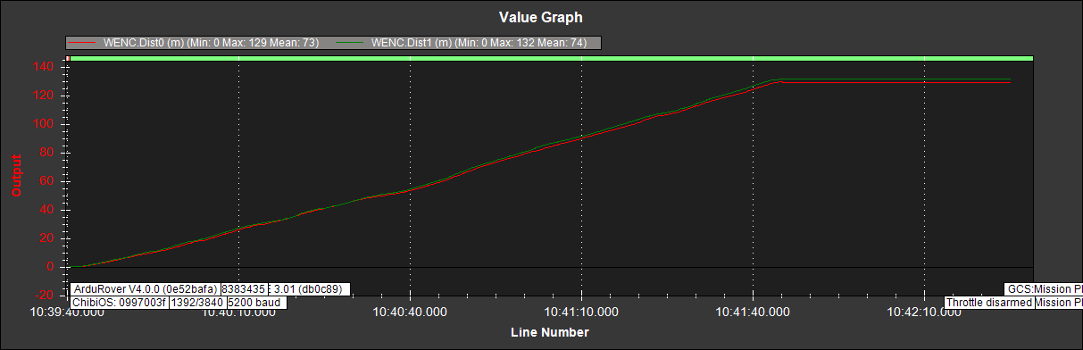
You can also check the WENC messages in the data flash logs after a mission. Plot WENC.Dist0 and WENC.Dist1 to see the distance traveled by the wheel encoders.
Thanks. That will be much more helpful now that I have verified normal operation. I had them swapped left to right and both wired the same, so forward motion showed one value rising and the other falling. Those issues were much easier to correct with ‘live’ data than pulling dataflash repeatedly!
Should I expect to see the wheel_distance messages in Inspector over a wireless link? It would be handy to correct that if it’s possible to do
This is the best debug method: the log with the WENC distances clarifies everything since you can check a real trajectory. See this and specially this.
I have the same problem. I reahttps://discuss.ardupilot.org/letter_avatar_proxy/v4/letter/h/ac8455/20.pngd that for companion computer it should be use telem port, not usb and I want to use odom data on computer. Is anyone knows how to redirect wheel_distance data to telem ports?
I don’t currently use a companion computer. As a guess I’d expect that you’d be reading Mavlink messages, not the raw odometry from the wheel encoders. In that case you’d be looking for the WENC. dist0 and WENC.dist1 messages for that data.
I haven’t been able to get the message over an RF link ever, but it shows when USB connected. If you get the message and you’ve followed the wiki for Encoder setup, you should see the values change based on wheel direction. If not, check your wiring (again) and make sure everything is going where it should. I don’t know if all of my settings are correct yet as I’ve only just got motion and dropped back to EKF2 to start tuning throttle and steering. I’ll get everything else working as expected before trying to add new complexity :).
Good luck, and post your solutions or problems!
I did follow the wiki…wiring seems good (i dont have an O-scope though). i double checked my config params. I did verify the encoders worked with the motor controller software though, and can see a voltage increase when going forward on my encoder input (to autopilot) when going forward and negative when going backward, so it seems the pins are being excited. Nothing in my data flash logs for the wenc1 or wenc2, all zeros…not sure where else to look…
I am using a Pixhawk 4 from holybro with the offboard distrobution board and some Servo City 313RPM motors with their enconders and their roboclaw 35A speed controllers. FWIW
Where are you sourcing Sensor Ground and Sensor Voltage+ from? Is the ground going to a pin on the connector back to the Pixhawk? It could be tempting to power the encoders from something like an external BEC and forget that the ground needs to be returned to the Pixhawk to provide a reference to the Channel A and Channel B signals.

