ArduPilot onboard OSD using an external SPI OSD breakout board


Using the ArduPilot onboard OSD is possible on board types that have an external SPI port accessible, including Pixhawk. All it requires is a MAX7456 type OSD SPI breakout board like this:
http://www.hobbytronics.co.uk/max7456-osd-breakout
and a few lines added in the respective board’s hwdef.

All OSD code processing is done onboard your flightcontroller. There’s no firmware processing for the OSD board required as it only carries the video chip circuitry. OSD settings handling is done via parameters just like with onboard OSD type hardware.

I have added OSD hardware to a revomini board using the SPI pins accessible on OPLink port:

@Rolf has done this on a pixhawk (fmuv3):

required changes to hwdef are:

  • adding the respective CS pin define
  • adding the OSD to the SPI device table
  • setting the OSD active and making the build system add the required font binaries:

see onboard OSD type flight controllers’ hwdefs for reference.

there might be other solutions coming up to support external backends to ArduPilot OSD on hardware without video overlay chipsets. this one imho is fairly easy to do on current code base and adds a noticeable amount of convenience and functionality compared to using 328p type standalone OSD hardware.

cheers, basti.

8 Likes

Basti I think you just saved a uart for a lot of people!
I didn’t know those breakouts existed!
@tridge this might be a reasonable default for external spi buses (or a good enough excuse to parametise spi)…

Are the LOS and RESET wires required to be connected too?

no, besides 5V and GND it needs the SPI pins only (CS, SCK, MOSI, MISO).

1 Like

Here is the wiring Pixhawk <-> Hobbytroic-Breakout
( https://www.hobbytronics.co.uk/max7456-osd-breakout )

Rolf

2 Likes

Where here the extra code required to run in the autopilot for this to work ?

in respective board’s hwdef

  1. define the CS pin on the external SPI port. on fmuv3 for example:
    PE4 OSD_CS CS

  2. add osd to SPI device table. on fmuv3 external SPI is SPI4. set ID, mode and speed:
    SPIDEV osd SPI4 DEVID1 OSD_CS MODE0 10*MHZ 10*MHZ

  3. add defines to set OSD active and include font binaries
    define OSD_ENABLED ENABLED
    ROMFS_WILDCARD libraries/AP_OSD/fonts/font*.bin

cheers, basti

If that could be useful for someone, The SPI4 definition and wiring for PixRacer
(But this is not tested yet, waiting for OSD breackout board to arrive)

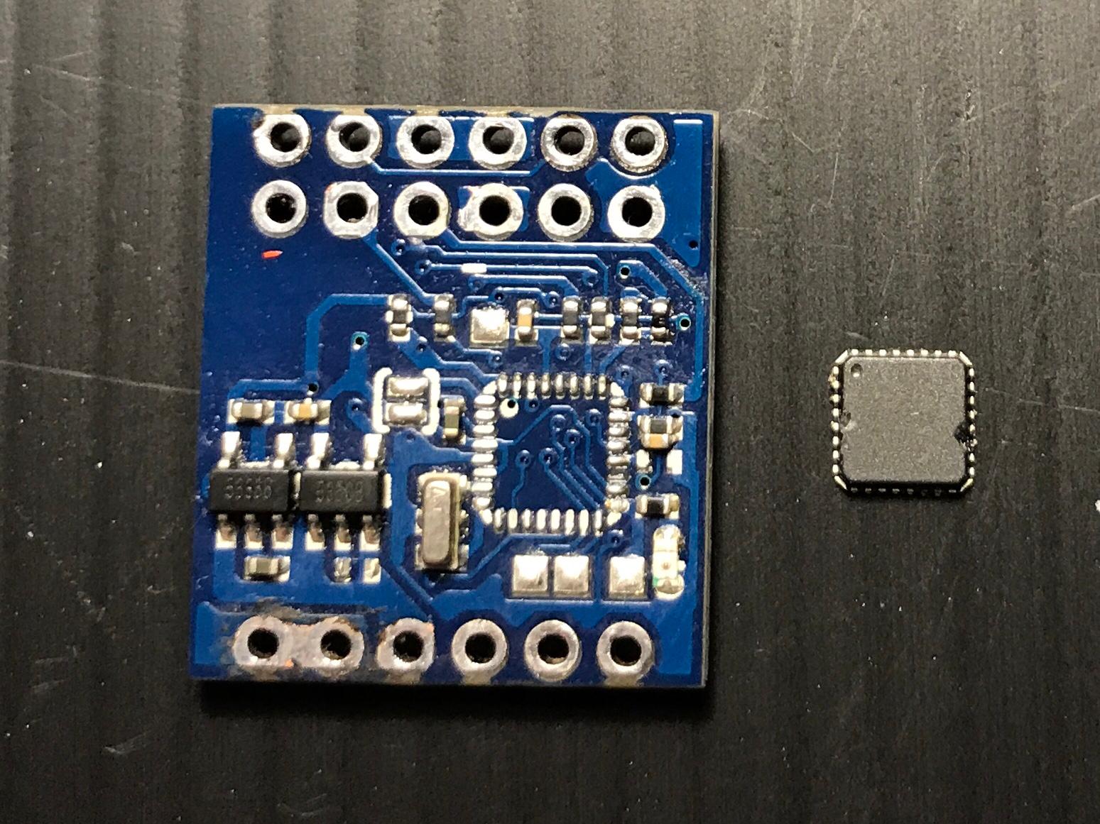
all those minimOSD boards catching dust didn’t let me rest, so i tried to modify an airbot microOSD and access the videochip’s SPI. i actually found that the airbot microOSD (the one i prefereably used as a standalone for the AB7456’s stability and low power consumption) does have SCK, MISO and MOSI exposed as solder-pads:

that’s pretty cool as it reduces delicate solderjobs to the CS pin. that’s pin 8 on the 7456 chip, connected to pin 10 (=PD6) on the 328p. so i took the atmega off:

the solder pads for SCK, MISO and MOSI can be routed to the UART pinheader pads that are not in use anymore without too much hassle. i then added an additional pin on the input side to connect CS to:


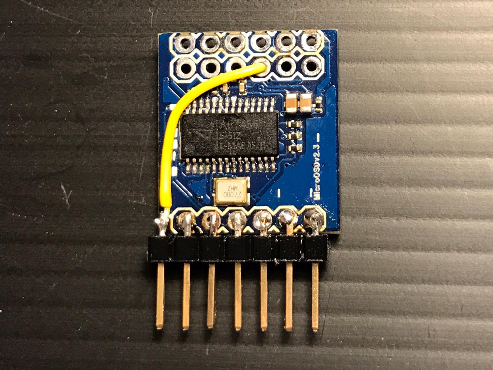
…aaaaand here’s my refurbished $5 32bit minimOSD:

cheers, basti.

5 Likes

Can’t get my Hobbytronics OSD breakout board to work with PixRacer.
Connected as I’ve described in my post above.

My hwdef change is https://github.com/SergeyBokhantsev/ardupilot/commit/317405f5e42273f77880162ac769ea921a0107a9

Firmware built and uploaded OK. Have set OSD_TYPE = 1 in my parameters.

I have a picture from my camera, but no any OSD text.

@vierfuffzig may be you will have a chance to look at my hwdef. Thought not sure if this a wiring or firmware problem. Any advice will be appreciated!

Ah, looks like I can only use “osd” name but not any free name in the definition:
SPIDEV osd SPI4 DEVID1 EXTSPI_CS MODE0 10MHZ 10MHZ

because it is hardcoded here:

Will try that.

@sergbokh did you get it to work? as you wrote too i do suppose the OSD_CS is required as well as adding the osd to the SPI device table:

cheers, basti.

Yes, all works great! The only problem was the SPIDEV name, as I wrote above.
Also I’ve set 2MHZ just for a case, because there is a relatively long wires. This seems didn’t affect anything.
image

nice, congrats! seems i missed your last post reg. device table, sorry.

basti.

How do I determine the correct DEVID when I change the SPI table?@vierfuffzig @sergbokh
In fact, I hope to configure a spi port on the pixracer for optical flow.

I may be wrong but for SPI devices I believe DEVID just need to be an unique number on the SPI bus. So if there is only device on SPI4 bus then DEVID1 should be OK.

@ucaszzw @sergbokh that’s how i did it too, successfully so far. just choose a unique identifier on the respective bus.

cheers, basti.

Hi!

I am new here, and i am new in ardupilot. I have a pixhawk 1 with six blheli_32 esc’s. The telemetry works great, but i want to see the esc’s current on osd. I ordered a MAX7456 breakout board, and connected it to SPI port. But how will it work? I dont’t know what is hwdef, or how can i modify it. Please can somebody write a step by step guide for me?

Thanks!
Laszlo

@kalalaa as for now adding an external SPI OSD backend to pixhawk type hardware requires individual changes to the respective board’s hardware definition file (hwdef) and compiling a customized firmware.
this http://ardupilot.org/dev/index.html is the best place to start for setting up a build environment.

on a sidenote, there’s a PR pending for adding the ext. SPI OSD defines to fmuv3 default firmwares. it’ll need some more effort from my side to get a decision if it adds any value though… https://github.com/ArduPilot/ardupilot/pull/11259

cheers, basti.

2 Likes