APM 2.8 can't connect to MissionPlanner via USB anymore?

:cry: this board was connecting fine to MissionPlanner not too long ago, maybe last week. i connected it today and it gives the error code
“Timeout waiting for autoscan/no mavlink device connected”
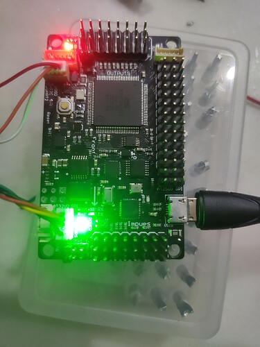
even though it’s lit up (stable green light, stable blue light, blinking red light) and connected to my laptop via one of the three usb ports (one of the two that isn’t USB 3.0)

i bought the board as “apm 2.8”

what do?

It’s possible that the signal wires are not making a good connection to the computer. Make sure the plug is seated correctly into both ends.
You should also hear some tones from the computer when it sees the APM board.
It’s also possible that your USB port number has changed.

Mike

I got a new cord and am using that… it was still giving me the MavLink timeout window.

so i tried something else from looking on here.

i have the ardupilot build of the Arduino IDE and tried to manually upload the firmware… i think i goofed though, it might not be the right coding, but the arduino returned a successful upload.

Code is as follows:

[code]#include <AP_Common.h>
#include <AP_Math.h>
#include <AP_Param.h>
#include <AP_Progmem.h>
#include <AP_ADC.h>
#include <AP_InertialSensor.h>

#include <AP_HAL.h>
#include <AP_HAL_AVR.h>

#include <PID.h>

// ArduPilot Hardware Abstraction Layer
const AP_HAL::HAL& hal = AP_HAL_AVR_APM2;

// MPU6050 accel/gyro chip
AP_InertialSensor_MPU6000 ins;

// Radio min/max values for each stick for my radio (worked out at beginning of article)
#define RC_THR_MIN 1070
#define RC_YAW_MIN 1068
#define RC_YAW_MAX 1915
#define RC_PIT_MIN 1077
#define RC_PIT_MAX 1915
#define RC_ROL_MIN 1090
#define RC_ROL_MAX 1913

// Motor numbers definitions
#define MOTOR_FL 2 // Front left
#define MOTOR_FR 0 // Front right
#define MOTOR_BL 1 // back left
#define MOTOR_BR 3 // back right

// Arduino map function
long map(long x, long in_min, long in_max, long out_min, long out_max)
{
return (x - in_min) * (out_max - out_min) / (in_max - in_min) + out_min;
}

#define wrap_180(x) (x < -180 ? x+360 : (x > 180 ? x - 360: x))

// PID array (6 pids, two for each axis)
PID pids[6];
#define PID_PITCH_RATE 0
#define PID_ROLL_RATE 1
#define PID_PITCH_STAB 2
#define PID_ROLL_STAB 3
#define PID_YAW_RATE 4
#define PID_YAW_STAB 5

void setup()
{
// Enable the motors and set at 490Hz update
hal.rcout->set_freq(0xF, 490);
hal.rcout->enable_mask(0xFF);

// PID Configuration
pids[PID_PITCH_RATE].kP(0.7);
pids[PID_PITCH_RATE].kI(1);
pids[PID_PITCH_RATE].imax(50);

pids[PID_ROLL_RATE].kP(0.7);
pids[PID_ROLL_RATE].kI(1);
pids[PID_ROLL_RATE].imax(50);

pids[PID_YAW_RATE].kP(2.7);
pids[PID_YAW_RATE].kI(1);
pids[PID_YAW_RATE].imax(50);

pids[PID_PITCH_STAB].kP(4.5);
pids[PID_ROLL_STAB].kP(4.5);
pids[PID_YAW_STAB].kP(10);

// Turn off Barometer to avoid bus collisions
hal.gpio->pinMode(40, GPIO_OUTPUT);
hal.gpio->write(40, 1);

// Turn on MPU6050 - quad must be kept still as gyros will calibrate
ins.init(AP_InertialSensor::COLD_START,
AP_InertialSensor::RATE_100HZ,
NULL);

// initialise sensor fusion on MPU6050 chip (aka DigitalMotionProcessing/DMP)
hal.scheduler->suspend_timer_procs(); // stop bus collisions
ins.dmp_init();
hal.scheduler->resume_timer_procs();

// We’re ready to go! Now over to loop()
}

void loop()
{
static float yaw_target = 0;
// Wait until new orientation data (normally 5ms max)
while (ins.num_samples_available() == 0);

uint16_t channels[8];

// Read RC transmitter and map to sensible values
hal.rcin->read(channels, 8);

long rcthr, rcyaw, rcpit, rcroll; // Variables to store radio in

rcthr = channels[2];
rcyaw = map(channels[3], RC_YAW_MIN, RC_YAW_MAX, -180, 180);
rcpit = map(channels[1], RC_PIT_MIN, RC_PIT_MAX, -45, 45);
rcroll = map(channels[0], RC_ROL_MIN, RC_ROL_MAX, -45, 45);

// Ask MPU6050 for orientation
ins.update();
float roll,pitch,yaw;
ins.quaternion.to_euler(&roll, &pitch, &yaw);
roll = ToDeg(roll) ;
pitch = ToDeg(pitch) ;
yaw = ToDeg(yaw) ;

// Ask MPU6050 for gyro data
Vector3f gyro = ins.get_gyro();
float gyroPitch = ToDeg(gyro.y), gyroRoll = ToDeg(gyro.x), gyroYaw = ToDeg(gyro.z);

// Do the magic
if(rcthr > RC_THR_MIN + 100) { // Throttle raised, turn on stablisation.
// Stablise PIDS
float pitch_stab_output = constrain(pids[PID_PITCH_STAB].get_pid((float)rcpit - pitch, 1), -250, 250);
float roll_stab_output = constrain(pids[PID_ROLL_STAB].get_pid((float)rcroll - roll, 1), -250, 250);
float yaw_stab_output = constrain(pids[PID_YAW_STAB].get_pid(wrap_180(yaw_target - yaw), 1), -360, 360);

// is pilot asking for yaw change - if so feed directly to rate pid (overwriting yaw stab output)
if(abs(rcyaw ) > 5) {
  yaw_stab_output = rcyaw;
  yaw_target = yaw;   // remember this yaw for when pilot stops
}

// rate PIDS
long pitch_output =  (long) constrain(pids[PID_PITCH_RATE].get_pid(pitch_stab_output - gyroPitch, 1), - 500, 500);  
long roll_output =  (long) constrain(pids[PID_ROLL_RATE].get_pid(roll_stab_output - gyroRoll, 1), -500, 500);  
long yaw_output =  (long) constrain(pids[PID_YAW_RATE].get_pid(yaw_stab_output - gyroYaw, 1), -500, 500);  

// mix pid outputs and send to the motors.
hal.rcout->write(MOTOR_FL, rcthr + roll_output + pitch_output - yaw_output);
hal.rcout->write(MOTOR_BL, rcthr + roll_output - pitch_output + yaw_output);
hal.rcout->write(MOTOR_FR, rcthr - roll_output + pitch_output + yaw_output);
hal.rcout->write(MOTOR_BR, rcthr - roll_output - pitch_output - yaw_output);

} else {
// motors off
hal.rcout->write(MOTOR_FL, 1000);
hal.rcout->write(MOTOR_BL, 1000);
hal.rcout->write(MOTOR_FR, 1000);
hal.rcout->write(MOTOR_BR, 1000);

// reset yaw target so we maintain this on takeoff
yaw_target = yaw;

// reset PID integrals whilst on the ground
for(int i=0; i<6; i++)
  pids[i].reset_I();

}
}

AP_HAL_MAIN();
[/code]

Now the board shows up as being COM3 instead of “AUTO” and baud is automatically set to 115200, it was not that under Device Manager, so i set it from 9600 to 115200, and set the Flow Control to “xon / xoff”

it is still timing out and giving me the error “No heartbeat packets recieved”

Now what ?

OK! so this is definitely a goof up. this program was open source code i picked up somewhere.

i found the actual program that is supposed to uploaded to the board shortly after, on GitHub

GitHub - ArduPilot/ardupilot: ArduPlane, ArduCopter, ArduRover, ArduSub source

the program is in C++ (.cpp file) and cannot be uploaded manually via the Arduino IDE because the format is not .pde

i guess my questions now are if i’m on the right track, and how I can go about converting the file formats over to .pde

again, still getting those 'No heartbeat …" error messages on the board in MP.

There is no such thing as Apm 2.8 :slight_smile:
Hint; you do not need to convert to pde, and we haven’t used Arduino for a long time, only make.

i’d really like some help correcting the problem, not hints no offense.

the apm board is based on an arduino mega.

no apm 2.8
it’s a chinese clone i believe, which is probably the reason for the misinfo

so anyway, how do i get this board talking to MP again?

first of all, this belong in hardware section of diydrones.com , as this is both in mission planner section (wrong forum) , and ardupilot.com is for 3DR products (AFAIK).

you need proper bootloader to load a Arduplane, ArduCopter or other ardupilot firmware, then when that boots, you’ll have a protocol called mavlink - which is what gives you telemetry and possibility to config/plan missions.

If you can’t just simply upload Ardu* firmware, the bootloader is bad/non-existing. In that case, (depending on hardware) you need first to flash it , (using for example usbtinyISP programmer)

I’m guessing that my questions were asked in the right place considering my posts have to be approved by the moderators before going live. besides, since this was a problem with mission planner to begin with, and this is the mission planner section…

alright, i googled some things that weren’t already evident…
copter.ardupilot.com/wiki/common … tmega32u2/

this board also has “APM MULTIPLATFORM AUTOPILOT v. 2.8.0” printed on the back.

there are no ‘JP2’ pins on this board, instead the jp2 pins are listed as “MAG” with “DFU” pins next to it.

none of the responses have really helped my original problem, where the mav link was timing out completely out of the blue after having functioned properly. How does the driver for the chip no longer work or exist just all of a sudden?

Honestly, if i could just convert the files from .CPP to .PDE, i bet i can get the board to function again through the arduino ide… considering i uploaded a different program to the board successfully already.

So, let me know if someone knows how to simply convert those files. for now, i’m going to tinker with what’s been posted above.

all of this other stuff is completely new to me and i have next to no idea what i’m doing, just as a heads up

you could just check out an older version from Git, I think we got the pde’s renamed this summer, but I don’t really think it compiled using arduino for years.
On the other hand - if you have the arduino bootloader on it, you should be able to upload any .hex , regardless where/how it’s compiled. (the .hex from Arduino is not different from any other .hex you would upload for a given device.)

well i followed the instructions for loading the .dll file that was supposedly missing… and then flip stopped working and the file also came up missing.

viewtopic.php?t=6064&p=36623

copter.ardupilot.com/wiki/common … tmega32u2/
these were the instructions. my clone board is ever so slightly different, but was still able to hard reset it and all that jazz, it just kept coming up with the same error code when i reloaded the bootloader, that the atusblib.dll (something like that name) was missing

i don’t understand what i’m doing wrong. the board however, can still be compiled via a special version of arduino ide made specifically for the APM flight board… not 100% because i gave up after having followed all your instructions and more further complicating things.

actually, i did find the old program and copypasta’d it into the IDE but the compiler came up with tons of errors when i hit ‘verify’

i am pretty sure i need to use a manual compiler like this because eventually i’m going to hook an Adafruit FONA or something similar to this board so i can run the drone via GSM/GPRS
learn.adafruit.com/adafruit-fon … e/overview

i am still figuring out how i’m going to hook the two up together, but i think one of the UART’s is not occupied, am i on the right track here ?

bump

still can’t get this board running properly

I have a arducopter apm 2.8 flight controller which worked fine for a week them when I went to set it up I plugged it into a usb but nothing it is getting power but my computer isn’t detecting it it’s not on device manager or anything my computer doesn’t even realise that I have plugged something in. I have tried removing the case I have tried different usb cables and I have tried a different computer but still nothing

Pls, i have been connecting my Air vehicle (F450 quadcopter) using APM 2.8 via USB and did all my configurations but all of a sudden, it does not light up anymore if connected to PC but lights up if connected to flight battery. This developed when I was troubleshooting why my ESCs are not taking instructions from RC controller to ARM my motors

It is very likely that your APM is fried, go get a pixhawk clone.

I was given an option of connecting my vehicle to MP via Telemetry instead of USB, i think i will try get that first, Notwithstanding, thanks for your support overtimes

The one upside to that is because the APM is obsolete you never have to update the firmware which you can only do thru USB. The downside is you can’t get logs thru telemetry.

Hello ppl,
Am new to this community. I have bought the apm2.8 flight controller recently. After all connections, i connected it to the Mission Planner and did all calibrations did some flight tests after that. The next day when i plugged the FC in the Mission Planner again, there was stable green light in the Power section but only red light blinking and become stable after few seconds and the drone didn’t seem to arm either. So i thought i need to calibrate again to arm it but the mission planner did not connect with Apm2.8 and gave me ‘No Heartbeat Packets Recieved’ . Not sure why and the board did not seem to have any damages or burnt(incase of short circuit). Iam not sure what iam missing at this point. I have attached bellow the picture of the apm2.8. Any suggestions or solutions would be helpful. Thanks

Ps. Iam aware this board has been discontinued long time back but it was the only one cost efficient.

That stopped being a case a long time ago. It is even less efficient if you consider time wasted digging through ancient documentation and dealing with problems you wouldn’t have had if you got a modern supported flight controller.

there is no need to buy an APM, there are controllers fully supported with more features built in like an osd and power sensor for half the price of an APM.

https://www.aliexpress.com/item/32828933953.html

Guess you are right. It’s better i move to latest FCs for better support when issues arise. Thanks anyways.