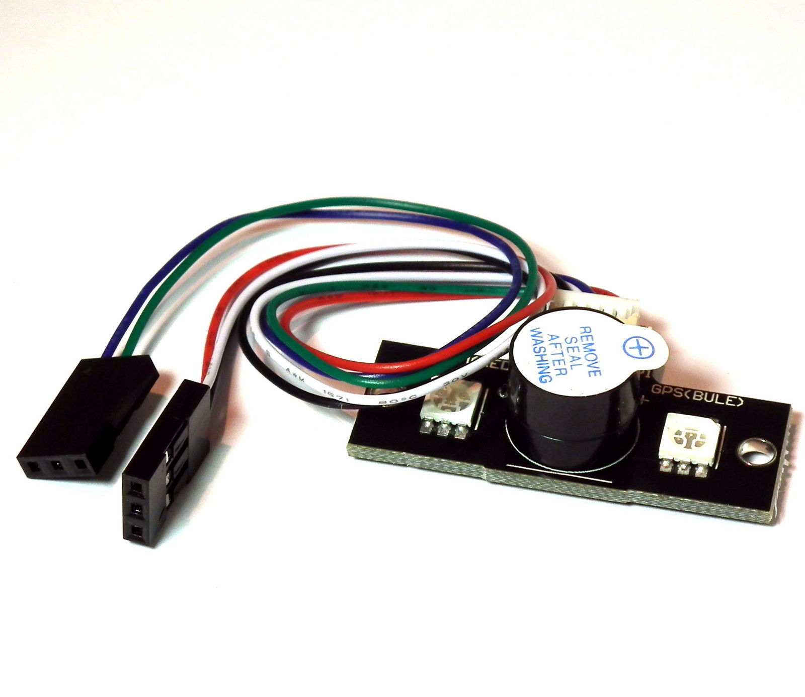
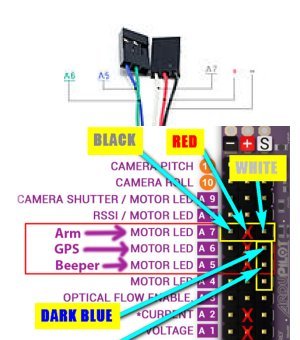
The only documentation I can find, is that posted by members of other forums, but none have indicated that there might be any problem. I’ve installed it using the illustrations attached.
The wire colours vary from my device, but the connections are the same
I checked the documentation for APM 2.6 and see that these pins can be set as relay pins or output pins. It also looks like there needs to be firmware to support that output which I am not familiar with.
I would check that the power rail is outputting 5v and that the signal pins are at 0 volts and change to 3.3 volts when on. If they are configured as relay pins then they are set as 54 - 62. 54 is A0, and 62 is A8. There are only 5 relays though starting at Relay and going to Relay4.
This is really a question for a developer to see if this is supported in the firmware.
Thanks Mike. I’ll have to do some reading to find out how to set the outputs.
The vendor has seen the photo of it NOT working and has offered to replace.
Thanks for your help.