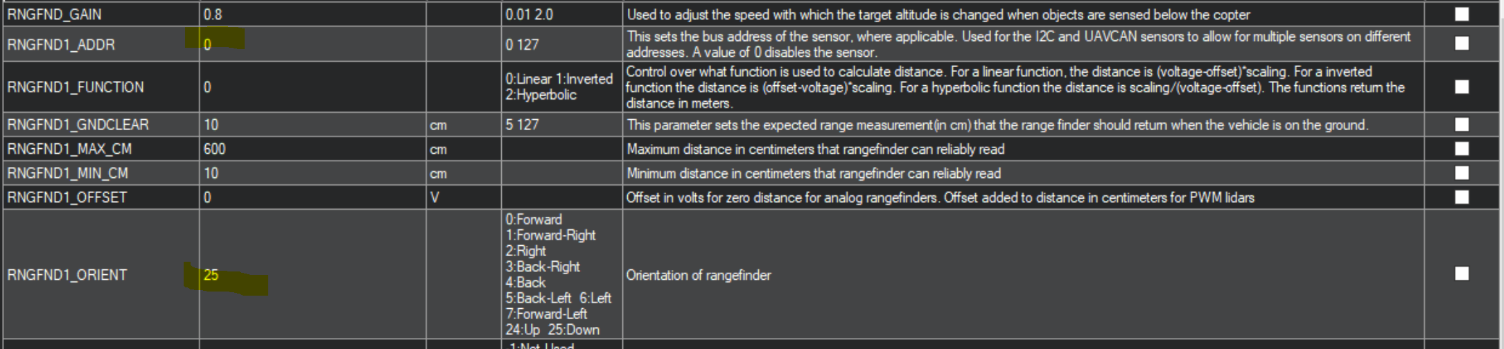
so on can node i must set 0 or 25…, 25 for set the sensor downface as i need
ok… i will test it with the last release ap periph for rangefinder firmware.
Ok so what am I doing wrong.
Arducopter 4.0.3
I am also using the F303 Universal FW
I have a TF mini connected to uart1 on the solder pads of a f303 node
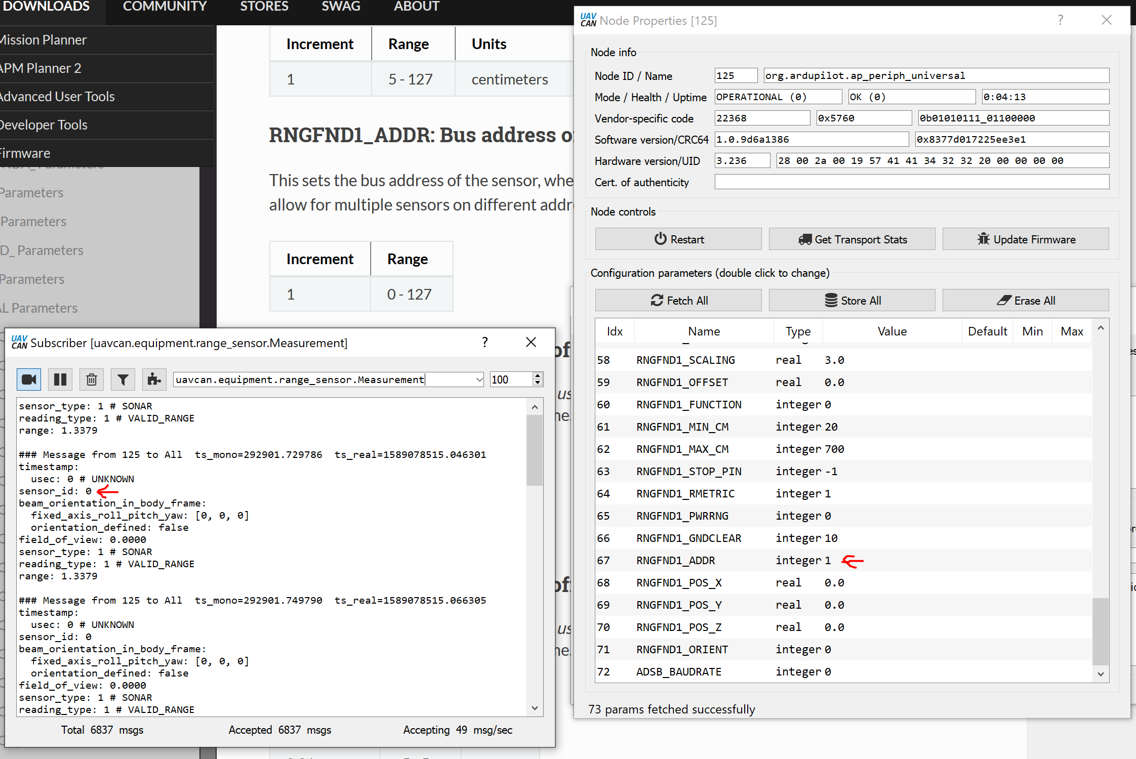
Here are my setting in UAVCAN
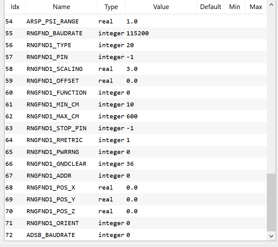
And in MP
Why does it say RNGFND1_ADDR 0 disables the sensor?
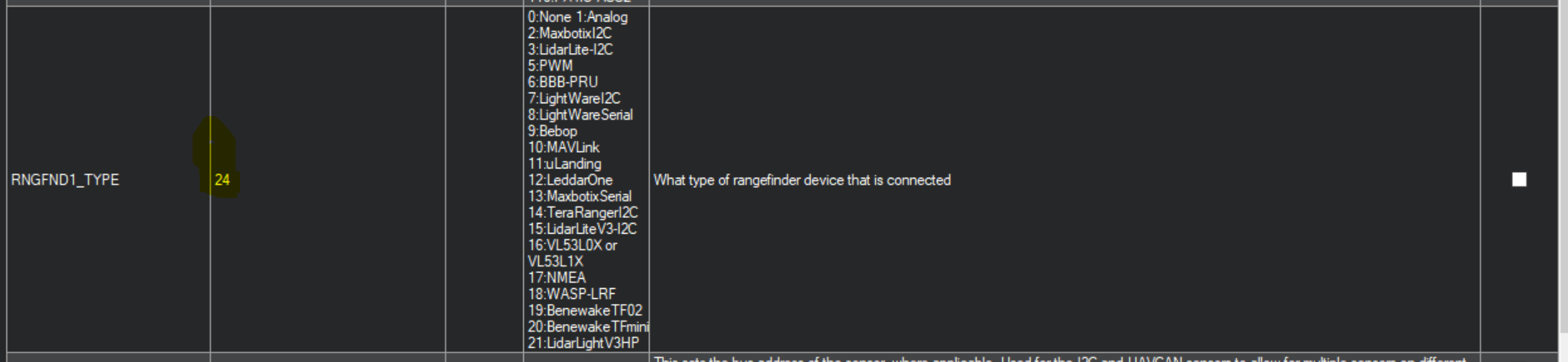
Set RNGFNDx_TYPE = 24 to enable UAVCAN rangefinder type. Rangefinder data received over UAVCAN will only be used if the received sensor_id matches the parameter RNGFNDx_ADDR . For AP_Periph firmware based adaptor nodes, this value is 0, so RNGFNDx_ADDR must be set to 0. Other UAVCAN rangefinders may differ. See also UAVCAN Adaptor Node instructions.
According to the above you must set orient to 0 on the F103/303 boards, unless I am reading that wrong
And another question  . There are two serial ports on that 303 board, do we need to specify which one the rangefinder is connected to?
*resolved I loaded each one to see what options were available
What is the difference between the 3 firmware files for the f303?
There is:
f303-M10025
f303-M10070
f303-Universal <- This one I have loaded and assume it includes all options
Thanks
Hi.
The M100# are mRo board designations for AP_Periph devices. To see how they differ, take a look at their hardware definition files:
f303-M10025 (mRo KitCAN) : https://github.com/ArduPilot/ardupilot/blob/master/libraries/AP_HAL_ChibiOS/hwdef/f303-M10025/hwdef.dat
f303-M10070 (mRo Location One) : https://github.com/ArduPilot/ardupilot/blob/master/libraries/AP_HAL_ChibiOS/hwdef/f303-M10070/hwdef.dat
f303-Universal (mRo CANNode) : https://github.com/ArduPilot/ardupilot/blob/master/libraries/AP_HAL_ChibiOS/hwdef/f303-Universal/hwdef.dat
This is how manufactures can offer customizes firmwares for different sensor set and orientations.
Serial 3 is the UART that we typically connect the GPS to in the GH6 connector, is it also exposed on RX1 and TX1 on the bottom of the board. The driver should loop thru the available serial ports. I think that RX2 and TX2 are being used for debugging messages.
Some times it is easy to have RX and TX reversed. Can you swap them and see if that helps? Lastly have you tried using UAVCAN GUI with your flight controller in SLCAN passthru mode to see the raw CAN messages? It would be helpful to know if there are any range finder messages being sent.
@pkocmoud I am seeing no range finder messages in the bus communications at all. I use a zubax babel board with uavcan
I assume the F303-Universal is the right firmware?
I started out on RX1/TX1 and nothing. Then tried RX2/Tx2
As far as the connections I have doubled checked to make sure the connections are 100% and tfmini rx goes to f303 tx and tfmini tx to f303rx
This is a new tfmini for me and I have no validated that it works. I will try that shortly
If it is working I am not sure why it’s not being picked up by the f303
Actually I have a couple tfmini’s that are in use on a couple other drones that I have. They even have a 6pin jst-gh connector on them.
I will try those.
What type of CAN messages should I see from the range finder on the bus?
Thanks
That is the correct firmware.
A logic probe would be helpful to confirm the serial traffic.
I have that same Babel adaptor. It works great. Are you getting node status messages from the CANNode?
Yes. I am getting a ton of those. But only those messages
In about 20 mins I am going to grab my second f303 and use it with a working tfmini and see what I see.
I will be plugging it into the 6pin plug on the F303
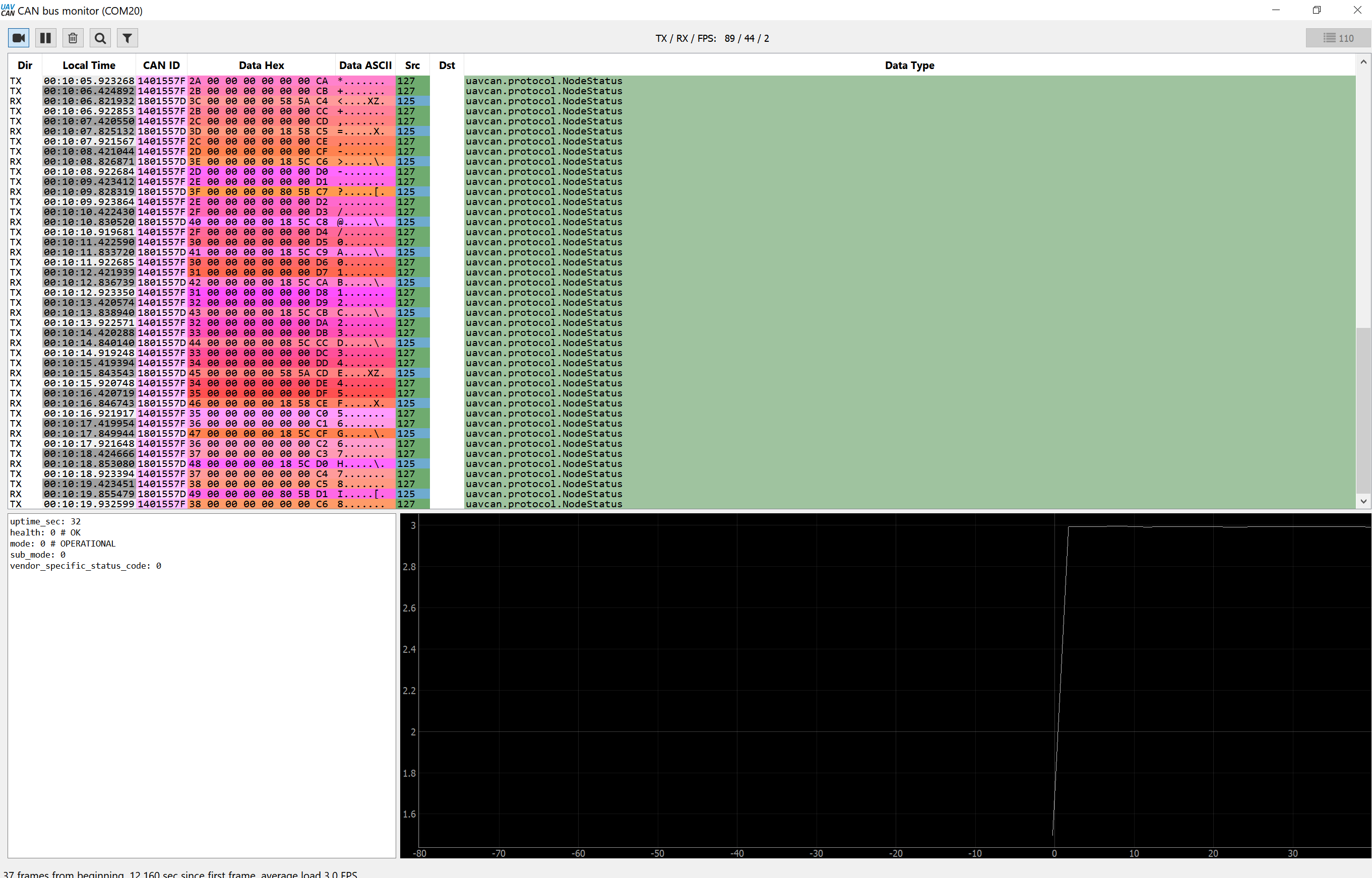
I just unplugged a working TFmini into my F303 board via the 6 Pin connector and the same lack of results.
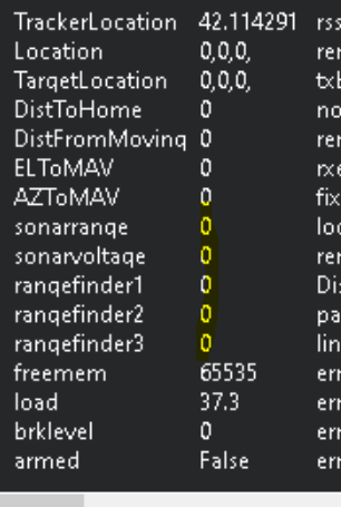
This is what I see when I monitor the bus.
Thinking out loud here… Does the F303 have the power needed to supply to the TFMini?
Good day, finally tf mini work on mro can node f, 103 " and sure on the f303…
Using the pads on the back of the board you don’t have issues power the sensor as if you are using the, 6 pin connector
Has anyone got lightware working over i2c on the CAN node?
2 things to consider when powering devices from a CANNode:
The CAN bus supplied power voltage will be at or just under 5v.
The CAN bus power has a 250mA resettable fuse so all the connected devices should draw less than 200mA. Otherwise power them externally.
Hi Evan,
I actually didn’t explicitly test with i2c (only serial), here’s the post on my findings.
Which rangefinder did you try. I tried with my TFmini plus and I could never get it to work at all. I was powering if off the f303 node, so maybe it didnt have the power needed for the rangefinder.
I have ordered another one and I will try when it comes in, only this time I will power the range finder off a BEC
Tried all weekend to get tfmini working with no luck, i have 2 uarts one connects fine to gps the other will not change to rangefinder looks to me like it’s set to sdout… orderd the tfminiS should be able to set that to i2c and see if that works…
I found a bug last night that might be causing some of the troubles. I hooked up a MaxbotixI2C sensor via I2C to a F303 CANNode. I could see the messages coming from the CANNode but not in Mission Planner set UAVCAN for RNGFND1_TYPE. I then noticed that I had to set RNGFND1_ADDR to 0 which works but was confusing because the Wiki states: “A value of 0 disables the sensor.” Then I went back to the APPeriph and changing the RNGFND1_ADDR did not reflect in the UAVCAN range_sensor message. So until this is resolved, there would be a limit of 1 UANCAN range finder running APPeriph.
1 Like
To help narrow down the issues. It would be very helpful to know which sensors are working and which are not.
Maxbotix MB1242 I2CXL-Maxsonar-EX4 works.
I tried a TF mini plus uart and that is not working, or at least I could not get it working.