Hello, you have done a very good choice with kitcan…with the new rm3100 you will fly as a sharm…ive tested a rm3100 and you will have awesom results, plus the baro on the board you will have a precise measurement…Mro know how make better all of that
Judging by the commentary on the product page, it isn’t immediately clear whether the KitCAN supports a variety of airspeed sensors, or if it is hard-coded to the MS5525.
The following implies that only the MS5525 is supported:
" . . . supports all legacy uBlox GPS sensors and a firmware that supports our MS5525 Airspeed Sensor (via I2C)."
The following instead implies that multiple sensor types are supported, by inclusion of the ARSP_TYPE parameter:
    Then access your KitCAN parameters this way via mission planner:

    Mission Planner->Initial Setup->Optional Hardware->UAVCAN-> SLCan Mode CAN1 (or 2) -> Parameters

    1 min later inside the CAN Parameters change the following:

    ARSP_TYPE -> 4
    ARSP_USE -> 1
    ARSP_BUS -> 0
I’d like to know as I prefer the SDP33 or DLVR on my builds, and it would be a great feature to allow installation of these particular sensors at a distance.
Hi Evan,
The simple answer is
This device runs Ardupilot supported AP_Periph, so any devices supported by the parent project can be supported by the CANNode. Our tutorial relates to a popular product we sell.
Complex answer is
On this board we expose a UART and I2C bus as well for optional devices. So you could also connect a GPS+MAG or i2c airspeed sensor as suggested.
If you have a look at the current airspeed driver, that value can be any on the I2C airspeed sensors:
enum airspeed_type {
    TYPE_NONE=0,
    TYPE_I2C_MS4525=1,
    TYPE_ANALOG=2,
    TYPE_I2C_MS5525=3,
    TYPE_I2C_MS5525_ADDRESS_1=4,
    TYPE_I2C_MS5525_ADDRESS_2=5,
    TYPE_I2C_SDP3X=6,
    TYPE_I2C_DLVR_5IN=7,
    TYPE_UAVCAN=8,
    TYPE_I2C_DLVR_10IN=9
One item of note, the DPS310 baro uses I2C device id 0x77, which is also one of the values that the MS5525 can be set to. So you would need to make sure that any I2C devices use a WHOAMI value other than 0x77.
I hope this answers your question, if not let me know.
2 Likes
yes, it supports all the I2C airspeed sensors that ArduPilot supports. It does not yet support the old analog sensors.
1 Like
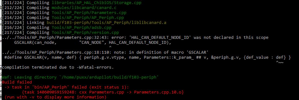
I just wanted to compile f103-periph with waf. Unfortunately, waf always stops with the following comment:
That is beyond my scope. I would like to use CAN to get far away airspeed sensor datas without interference.
don’t build f103-periph, it is a base set of definitions and is not meant to be built. Instead build a derived target like f103-GPS
Thanks a lot - f103GPS build works
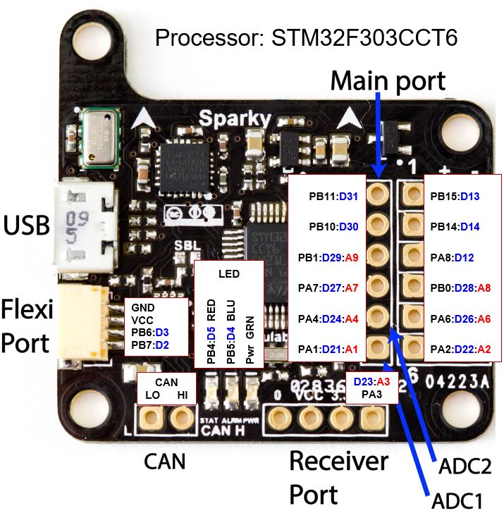
So far so good with AP_Periph nodes via Arduino IDE. I have a couple of Sparky V1 F3’s (https://github.com/geosmall/Sparky_FCs_for_Arduino_Core_STM32) I am working toward converting to AP_Periph nodes. The Tau Labs folks were ahead of their time, their Sparky boards are ideal with already built-in CAN transceivers. See CAN pins below:
I also have a few Sparky V2 F405 flight controllers I would like to work to convert to AP_Periph nodes.
How hard would it be create an F405_periph base bootloader? I’m hoping not too hard as they are already supported AP Chibios targets?
yes, very easy. Have a look at the CUAV_GPS, it is a F412 based AP_Periph GPS. Your hwdef.dat and hwdef-bl.dat will be very similar:
Good day, its possible use dual can node board for attach more supported periph?
you can certainly use two CAN nodes. We don’t yet support two CAN interfaces on one CAN node. I do plan to add that, but not done yet.
Knowing that the CANBUS is insensitive to interferences, you really want to know it:
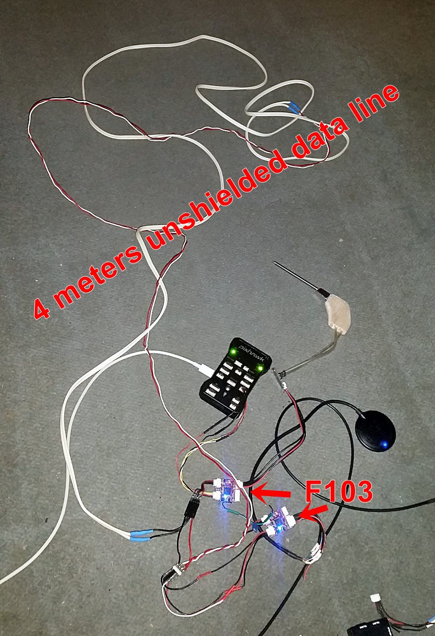
Between Pixhawk and mRo 103 nodes there are 4 meters of unshielded speaker cable respectively wire used for a doorbell (CANBUS high + low).
This distance would be impossible with an unshielded I2C bus. With Tridge’s AP_Periph Firmware, CAN BUS and two mRo 103 nodes the connection works fine without any disturbances and only 4 wires between Pixhawk and GPS (including NTRIP data upstream !), compass and airspeed sensor.
Does the f103 have enough power to control ESCs and / or servos too ?
nice test, thanks!
Depends how it is controlling them. If it is just outputting PWM or DShot then yes, I’d expect it would have no trouble, but I’d far prefer to use the f303, especially for DShot, as the DMA on the f103 is a pain.
thank you for your response… i will prepare a cable so i can use a second can node coz on my fc I’ve only one CAN port.
Good day, would you mind advice me pls for the correct firmware file for update the Kitcan Node by mro… there is also a param i can use to enable/disable the arm switch of the node in MP?
Waiting for a kind response
Hi Dave. There is currently no param to enable / disable the arm switch. It is an option that gets built into the firmware.
Here is a link to the latest mRo m10025 firmware. https://github.com/mRoboticsIO/Firmware/tree/master/M10025_KITCAN . Please let me know if you need any assistance.
1 Like
I’m working through some challenges getting a custom node to load with AP_Periph bootloader. I think I have all the steps in place including watchdog pat but appear to be getting an IWDG reset with an error code 15 in UAVCAN GUI.
I see that there are provisions for printf debugging messages (e.g. https://github.com/ArduPilot/ardupilot/blob/master/Tools/AP_Bootloader/can.cpp#L578). Are these enabled by default in f103-GPS_bl or do they need a compile switch and rebuild? Also how to tell USARTn and pins?
Best Regards,
George
I’m still trying to get debug info from AP_Periph bootloader running on a F103 based platform.
I see printf() statements sprinked throughout the bootloader code example:
And it appears to be directed to SD1 (which I assume to be STM32 USART1?)
From auto-generated hwdef.h in the build folder USART1 TX/RX appears to be on PA9/PA10, but I’m not getting any output there.
I’m missing something, just not sure what or where to look. Any breadcumbs would be most welcomed.
Given error code 15 most likely the board is locking up. The way I would normally debug this sort of issue is to either use a debugger or use GPIO toggles.
Assuming you don’t have a debugger setup for this board then GPIO toggles are the way to go. These are the most reliable way to get a small amount of information out. The aim of the GPIO toggles is to narrow down where you are getting to in the startup code.
What you do is setup a GPIO output pin in hwdef.dat then use palToggleLine() to toggle the pin between high and low a distinctive number of times, watching with a logic analyser (eg. Saleae) to see what is happening.
This sort of GPIO toggle can be used very early in the startup, before serial ports are initialised.
For a fancy version of this which writes strings see this code:
you don’t really need anything so fancy for this debugging. You’re just trying to narrow down what section of setup() or loop() you are getting to.
It does assume you have a logic analyser though. If you don’t have one then get one, as it really is an essential tool for board bringup.
Also, post a link to your hwdef.dat in case there is something easy to spot in it.
Cheers, Tridge
Thanks for the guidance. I have a Segger J-Link debugger and Saleae logic probe available. I’ll give the GPIO toggle a try.
Best Regards,
George