I am working on a new PDB for a Quadplane and need to find the circuit for a current sensor would like it to be a hall sensor but a shunt resistor will work as well.
Let me know please and thanks…
I am working on a new PDB for a Quadplane and need to find the circuit for a current sensor would like it to be a hall sensor but a shunt resistor will work as well.
Let me know please and thanks…
Not a circuit diagram but plenty of sensors here
https://www.robotshop.com/en/current-voltage-sensors.html
You could check their specs and decide on something that might work and then build that same circuit into your design. Most of them will be using the text-book circuit from the IC manufacturer.
Warning: the bidirectional ones will have offset voltages and funny stuff in the output
Hey thanks Shawn
I really am looking for the schematic. I ahve a new PDB under development for the quadplane.
I’ve never done schematics or layouts for hall effect sensors but have done a few for current shunts.
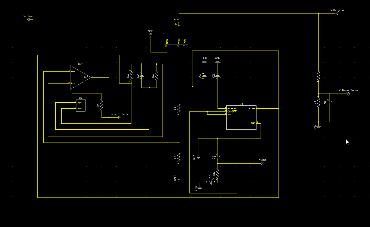
The general idea from your schematic seems to be Voutput from current sense that is then Voltage divided. Next, you likely have a non-inverting opamp circuit with a low pass filter.
The objective is to choose the voltage division ratio and the non-inverting opamp ratio such that you reduce the sensor output to be 3.3V compliant (I’m guessing your objective here). The ratios should be such that get to use the full ratio of your ADC.
The equations for these basic opamp circuits are easy to find once you find the form.
Could notes on your schematic:
Convention has inputs on left side and outputs or right : So battery_in (left) to drone_esc (right).
You should try to rearrange the opamp circuit to match the normal forms so that it is easier to help.
Hey Josh.
Thanks for you feedback. To be honest I have not done a schematic like this is 40 years and never with hall sensors. Also I don’t care if it’s a hall sensor or Shunt resistor. I just need a schematic that is known to work. This one I backward engineered from a working sensor I have used. But I can’t be sure of all the values. So if you know where a Pixhawk compliant sensor schematic is, please send me that way.
As for the layout form. This is good information. As I said first one in many a year.
use a hall sensor, much more precise than resistors, but most importantly for you: it’s really just a LDO and 3 filtering caps in addition, so much simpler, no critical component values = it will just work … don’t waste your time with shunt, op and blabla  (look at a mauch sensor, and count the components…)
one point to look at is that many are 5V while you would prefer 3.3V ratiometric ones, if you only get a 5V ratiometric one, like the popular ACS770, simply add a voltage devider at it’s output, design is again quite uncritical becasue the sensor outputs are low impedance
(teh 5V ones you even could run without the LDO, but with the 5.3V for your pixhawk, like one does with the Mauch sensors)(not ideal, but can’t be beaten in terms of parts count and simplicity)
if you still have second guesses, I could send you the part of a schematics of the UC4H powerbrick I’m using since years, but as said, you really can’t make it to fail…
hi @olliw42
Thank you for jumping in.
so first my preference is the hall sensor and I did do the parts count from the Mauch sensor. In fact, I didn’t’ want to say it out loud but I reverse engineered the Mauch sensor and came up with the schematic above. The thing is I know nothing about this tech. When I was doing circuits I was a teenager and TV’s still had tubes. Op amps where just making their debut and I never stayed up on it.
The only thing I have been able to learn from this is the LDO is providing a 4vdc output to the hall sensor to I think avoid measurement changes due to voltage sag.
This is about the extent so far.
maybe I shouldn’t have referenced to teh mauch sensors since I actually haven’t looked at them for a long while, so may have changed
but it’s really as simple, use a LDO with two caps (one at input, one at output, C3, C4 in your scheme) to reduce the 5.3V to something in the range of the hall sensor, if you use an adjustable LDO to e.g. get 4.8 V you will have two R’s in addition. Also add a cap at the output of the hall sensor, and 2 R’s for a voltage devider, pretty much like it’s done with R1,R2,C2 in your schematics, that is your R7 and R5 with a cap in parallel to R5. That’s for a 5V ratiometric sensor. In your scheme you can drop C3, and obviously R6, D1, as well as all the stuff which comes behind R5 (but add a suitable cap parallel to R5).
4V for the LDO looks a bit dodgy, since it would be out of spec for the common ACS sensors, that’s why I used an adjutable and set it to 4.8V or so. But there might be other Allegro sensors ther this is perfect.
If you can get a 3.3V ratiometric sensor (they exist!), it’s just a 3.3V LDO with two caps, and the sensor with a cap at it’s output.
the hardest thing in the game is to find a hall sensor type one likes and which also is available in some store
btw, are you using Eagle?
I am using Diptrace.
I started using it because a friend was showing me how to build a board sometime back and I just stuck with it.
So the first part of this circuit seems easy and that’s the voltage divider and the LDO.
I found the this LDO, it appears to be the one that is on the mauch sensor so I assume it should work ok.
This version is 5vdc out.
https://www.digikey.ca/en/products/detail/texas-instruments/LP2985IM5X-5-0-NOPB/367680
So question.
You referencing this in your last update.
Also add a cap at the output of the hall sensor, and 2 R’s for a voltage divider, pretty much like it’s done with R1,R2,C2 in your schematics,
Are you saying pop a voltage divider on the output of the LDO to get say 4.8 volts.
I added in a Mx4213 Op Amp after the Hall Sensor output. I got this from an experiment with Arduino so I assume it’s compatible.
Thank you
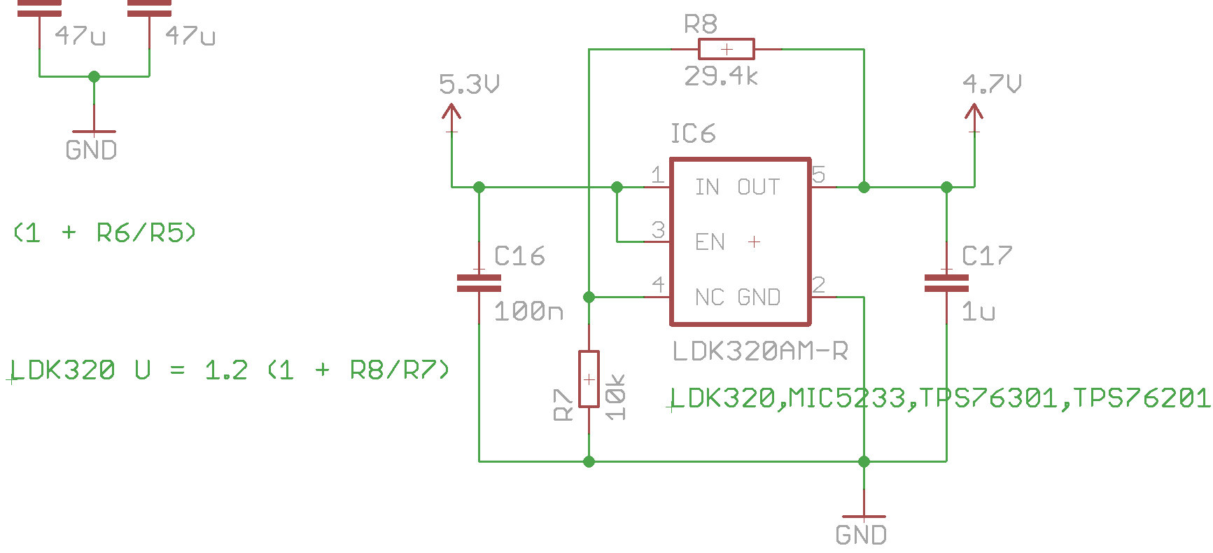
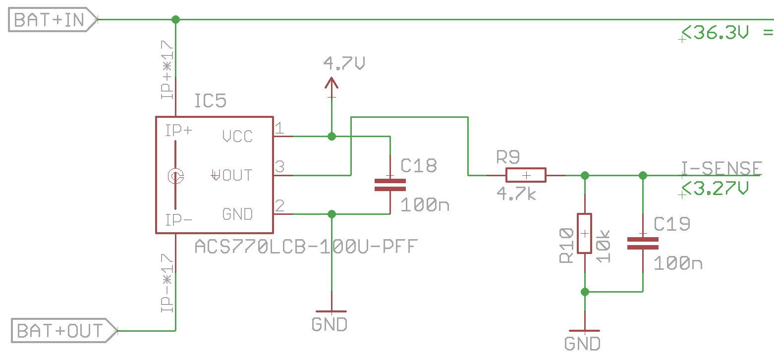
here the cutouts of the u4h power brick scheme, showing the LDO part and hall sensor part (don’t get confused by things which are half shown, they do not belong to what you need). The LDO is a LDK320, and the hall a ACS770
I did use the ACS770 since I couldn’t get a 3.3V sensor at that time, so I reduced the voltage to 4.7 V, to have sufficient room to the 5.3 V main supply (even an LDO needs some voltage drop) as well as to stay in the 4.5-5.5 V recommended operation voltage of the ACS770. You see two caps for the LDO, plus two R’s to adjust it’s voltage, and R9,R10, C19 forms the voltage devider with a cap parallel to R10 to filter, which is what I was talking about. You can use larger capacitances like 1u or even 10u for C19. Lastly, C18 to filter the sensor’s VCC, but it is not absolutely needed.
The ACS758 is one of the more interesting ones. The data sheets says it can operate at 3.3V, so with this one you really could go the simplest way, just a 3.3V LDO with two caps, and the sensor with an output cap (if you want you can throw in an additional R in series to form a LPF), but the datasheet also says that some performance/accuracy metrics are only guaranteed in the range of 4.5 - 5.5 V. But I guess it would just do fine unless you want super accurate results.
A 5V LDO would not be what I would use, unless your main voltage is 5.5V or larger, all LDOs need some drop voltage, so the 0.3V from 5.3V to 5V can be too tight. It may perfectly work, since 0.3V is “a lot”, but if your main voltage sags to 5.1 V (which easily happens if you draw 1-2 amps), then it may not be sufficient. Hence I went with 4.7 V.
If you would have used Eagle I just would have send you my Eagle files, but that’s obviously not an option.
I think you should have now plenty of food to get along with your design 
EDIT: your scheme won’t work
Wow @olliw42
Thank you ever so much.
I didn’t’ think my schematic would work.
This is awesome I can’t thank you enough.
Now to go do some more reading and put this all together.
I did have one question and that was around the NC connection on the LDO.
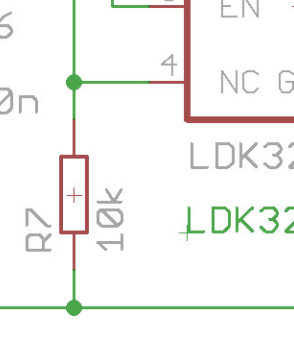
I assume that’s actually the ADJ pin on the adjustable version. It’s NC on the non adjustable.
Thanks again.
yes, you are absolutely correct
I apparently was too lazy to do a new symbol just for this …
It sounds like you might have the info you need but if you have anymore uncertainty, I can send you the schematic for the power distribution board I did.
It uses the same current sensor as the 200 amp Mauch. It also has the op amp circuit to make full use of a 0-3.3V ADC input.
I would love to see it Mark.
While I think I am on my way. I would like to look, for me this is a learning opportunity.
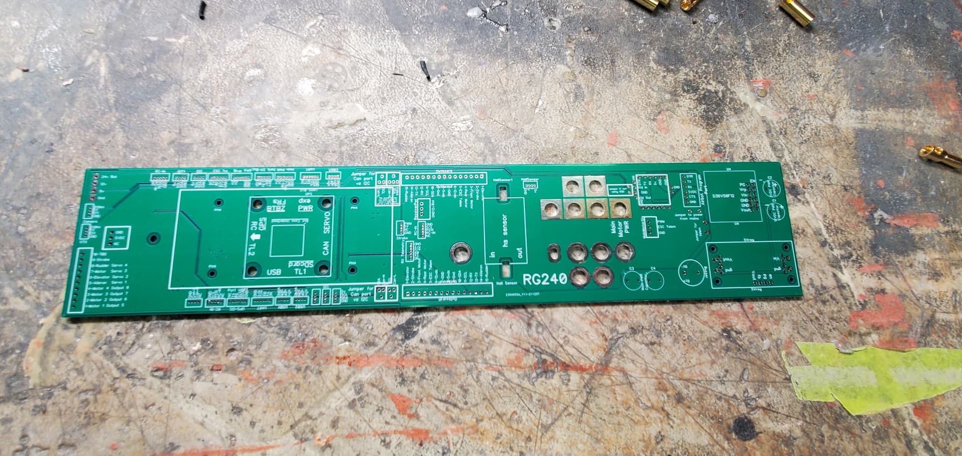
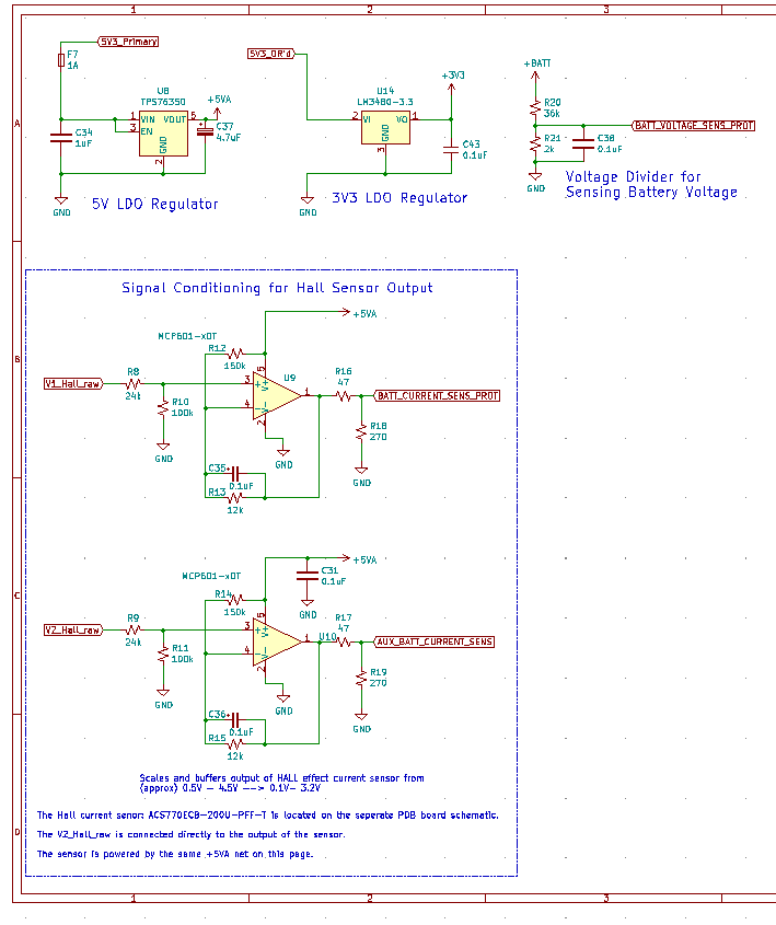
The whole schematic is quite large (this same board is also a CUBE carrier) so I will just post a screen shot of the relevant area.
To help you picture what is going on here: there are actually two stacked PCBs, one contains all the small components that needed narrow, dense traces, and the other (PDB) contains the hall effect current sensor, safety cut off MOSFETS, with thicker copper. The appropriate signals are connected with stackable headers between them.
So, the actual current sensor is on the PDB (and a single decoupling cap), whereas the other components such as LDO and OPAMP, …ect, is on the carrier board.
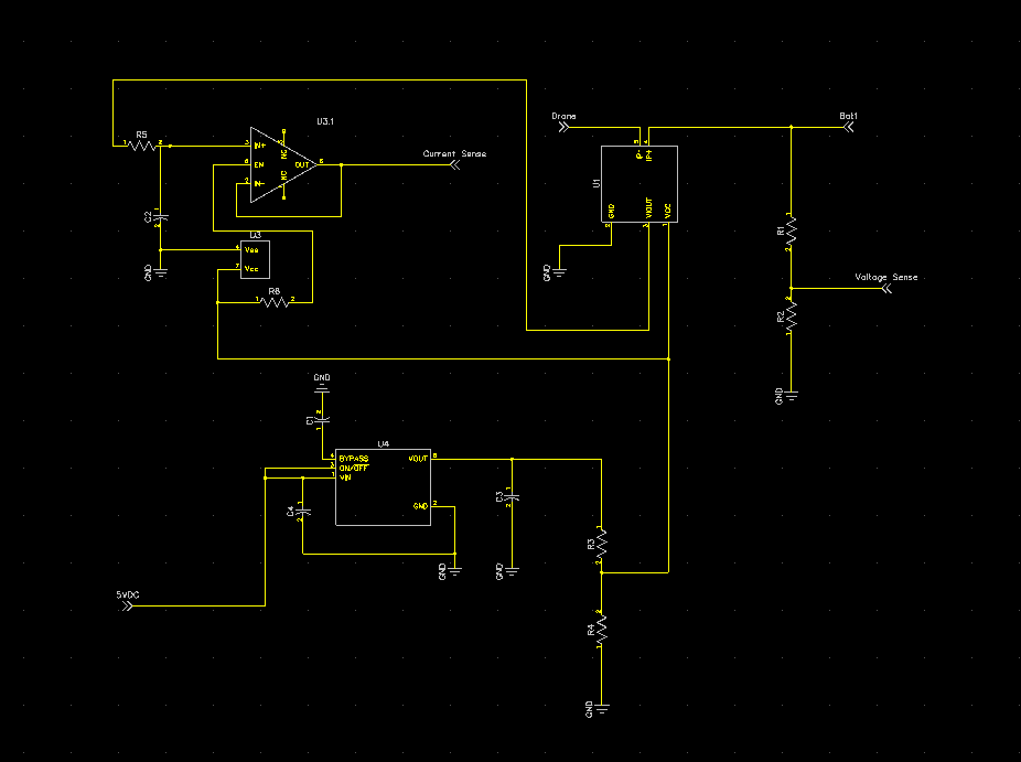
Here is most of the support components for the current sensor (and a few nonrelated things, hence the 3v3 regulator)
Keep in mind there are two current sensors in my design, so you only need one OPAMP per sensor.
BATT_CURRENT_SENS_PROT and AUX_BATT_CURRENT_SENS connect directly to the CUBEs inputs of the same name (the normal ones you would use with any external sensor)
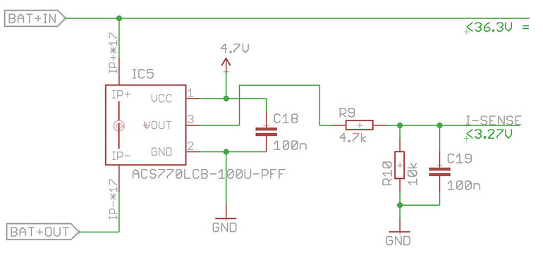
And here is where the current sensor itself is connected:
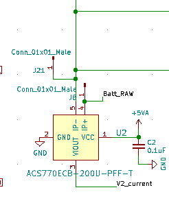
IP+ is directly connected to the battery, IP- is the downstream side of the sensor. V2_current is directly connected to V2_Hall_raw on the other PCB.
Also, if you wish direct message me your email, and I can send you the entire KiCad project if you want to poke around and get ideas. We are open sourcing the design but haven’t settled on a license yet. Once we do, I can post it publicly on the forum.
In case you can’t really see what’s going on, here are PDFs of those pages:
PDB.pdf (64.8 KB)
PowerSense_conditioning-PowerSense_conditioning.pdf (66.6 KB)
Wow this is great thank you sir.
Have a super Christmas and a Happy New year.
Thank you for all your help.
thanks mark for your reply and help.
Hi Shawn, @xfacta I’m building a current sensor pretty much identical to the circuit here. Just wondering what the issue you had with the bidirectional hall effect sensors. I know they have a voltage offset, but this can be removed by using the voltage offset parameter in arducopter and calibrating using a current meter.
Nothing more, you’ll be fine since you are aware of those things