new to all this autopilot wizz.
I’m trying to fit a pixhawk 2.4.8 to a large rover.
mostly going well so far, just stumbling over a minor thing.
Im trying to get two sets of voltage and current data into the pixhawk. Because of some ‘interesting’ design requirements they are being radioed from the ESCs (vesc 4.12) to a micro (teensy 4.1) up by the pixhawk.
What would you guys suggestions be for getting the data from the micro into the pixhawk?
my first guess was the analogue inputs, but I’m running two banks of 36V lead acids (~42v peak) so the resolution is poor when crammed into a 3.3V ADC. Rather noisy too. Is there a way to set the value the pixhawk reads at 0v. Ie rather than it being 0-45v for the full input range , could it be changed to 30-45v ?
Mavlink looks like a great do-everything option. But all the librarys I’ve found for it appear to be dead, and it looks like a lot of hassle to fix just for the limited things I wanted it for currently. Does anyone have a library that works?
there’s a lot to research and most options aren’t made for this sort of bodging so any advice or insight would be appreciated.
Your options with that flight controller are the Power Inputs (Voltage and current) at 3.3V max, An ADC input at 3.3V max or a ADC input at 6.6V max which has a voltage divider on the input. You have to scale your signals to these max values.
ok, thats interesting. I was getting noise equivalent to a few volts from a constant input.
i’ll double check everything but i wouldn’t expect that much noise from how its setup.
at least I know it should be possible.
thankyou
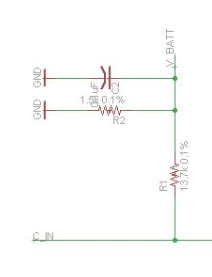
The original 3DR voltage sensor is simple yet effective, there’s a 0.1uF cap to remove noise. Just change the resistor values to suit the maximum voltage (and output scaled to 3.3v)
In this diagram “C_IN” is the actual battery supply + , and “V_BATT” is the sensor output (max 3.3v)
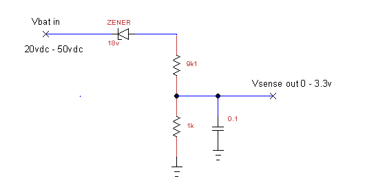
Here’s a circuit to measure within a range using standard value components, use metal film resistors.
The zener will probably be effected by temperature, so keep it away from other hot components, or calibrate the whole circuit once everything has reached operating temperature.
I haven’t tried this myself - as Eosbandi said the conventional voltage divider style gives plenty of resolution.
got it wroking better, its still not perfect. but it will do for the time being.
the pixhawk (or one of its peripherals) was drawing burst of current, causing slight drops on the power line. that drop was reflected on the micros output. should have known better rearly, thankyou eosbandi for pointing out it was within its capacities.
xfacta, i’m outputting the voltage as a PWM from a 3.3v micro, so all I need is a standard RC filter.
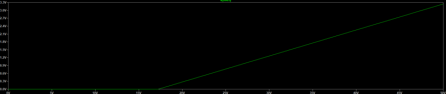
that second circuit caught my eye so it simulated it. here’s the output.
it ignores the low end of the battery voltage which would give you higher effective resolution from the adc, unfortunately i don’t think there’s a way of telling the pixhawk this (if there is that would be useful), its expecting a linear relation between battery voltage and the ADC so it wouldn’t report it correctly.