I’ve started using DroneCAN for many devices, including all servos and GPS. I now require more physical connection ports (/there are only 6 coming out of the included CAN board). Does anyone know of any board compatible with ardupilot which increases the number of physical CAN connections? Or can I simply daisy chain another of the included boards to increase the number of CAN connections? If so, what is the limit of in number of connections in doing that?
I require 12 CAN connections.
CAN uses a daisy chain topology with 120 Ohm termination resistors at both ends of that daisy chain. The CAN board violates that by providing a star-like topology. And that will reduce the maximum allowable cable length and the max allowable devices. So there is no number fits all here. you deviate from the standard, so the standard no longer applies to you.
Theoretically you can have up-to 255 devices on the BUS. Try it.
If does not work, reduce the wire lengths and move to a more chain-like topology.
What you must observe at all times is the rule that only the two furthest devices have the 120 Ohm termination resistor active.
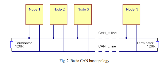
We can read:
The high speed ISO 11898-2 CAN standard defines a single line structure network topology.
CAN bus does not support star or even a multi star topologies.
Depending of the size, you can probably make short star topology using I2C type expander boards, just make sure it is terminated properly.
Just google Pixhawk JST GH I2C Bus Splitter
I work with the 6 ports
I inject power from UBEC using JST GH connector, but in that case, just make sure you disconnect VCC to the connector going to the Flight Controller
I found that one. But I need 12-14 connectors. Where have you put the second 120 Ohm resistor? On one end the cube has one internally, but another one should be present, correct?
The diagram above can be easily replicated by DaisyChaining multiple I2C splitters, what is problematic is the length of the branches, you need to keep them as short as possible to avoid bus desync when running at 1Mbps
Technically you dont have to connect ground as the CanBus transceiver are Push-Pull and can be “floating”. In some case this is necessary to prevent floating grounds and offer glavanic isolation.
How long can these branches be? I would need them to be around 2-3 meters each… Almost all comms are servos, so there won’t be very much data. I don’t need the horizontal wires to be very long.
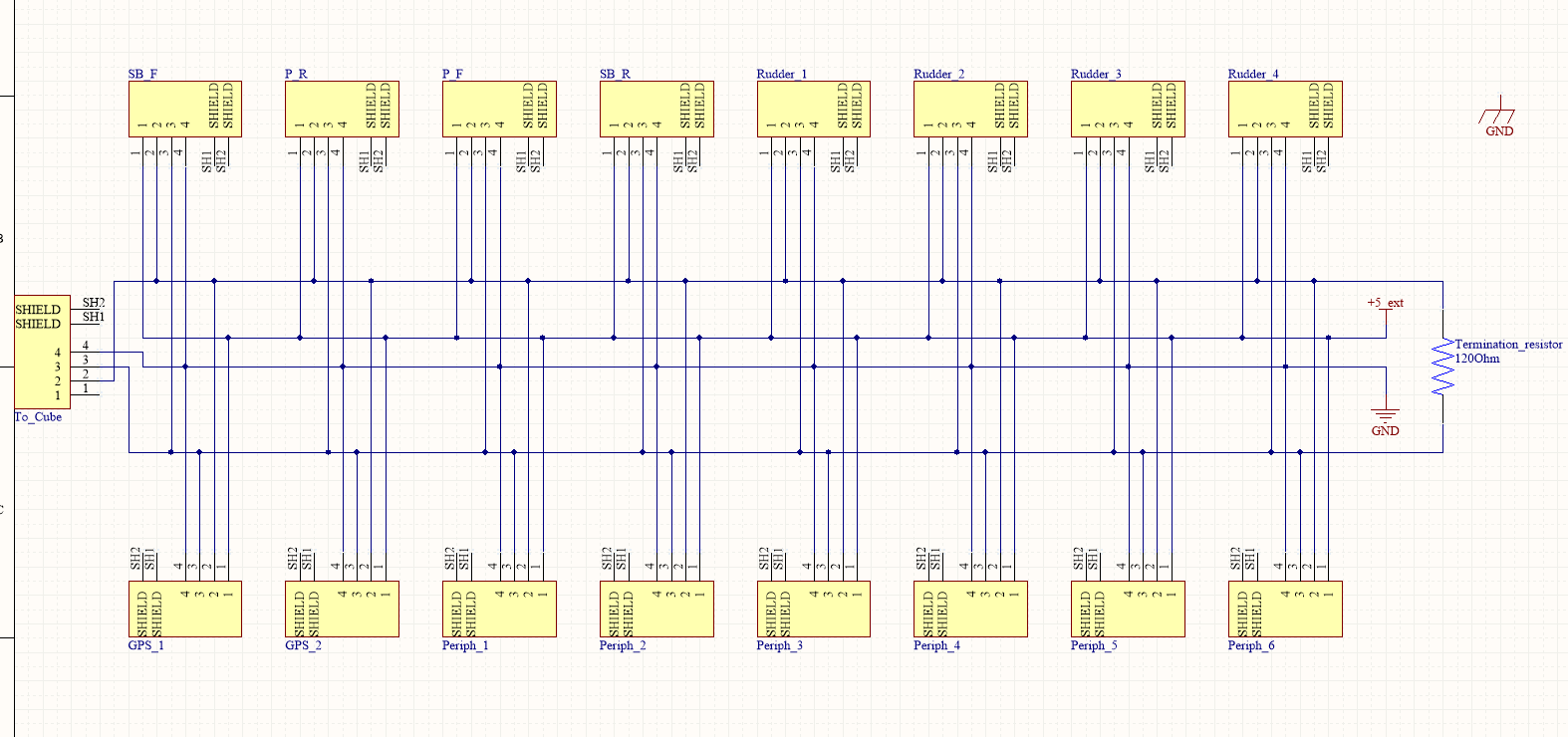
I am wondering, doesn’t the schematic I sent use the basic CAN topology from the link you sent? Shouldn’t that then offer the best performance? If not, how should I wire them? Any suggestion is greatly appreciated.
I’ve been thinking and I think I understand how it should be done “properly”. I suppose, that from the connector called “To cube” I should connect the bus-cable (CAN-HI, CAN-LO), then run the same cable to each and every device and splice each of the devices with a short cable into the “bus-cable” and lastly, connect the bus cable to the board where another termination 120 ohm is present. Right?
Yes I remade the design and now it’s a CAN bus cable which runs through the entire UAV and from there servos are connected to the bus via a roughly 50 cm cable.