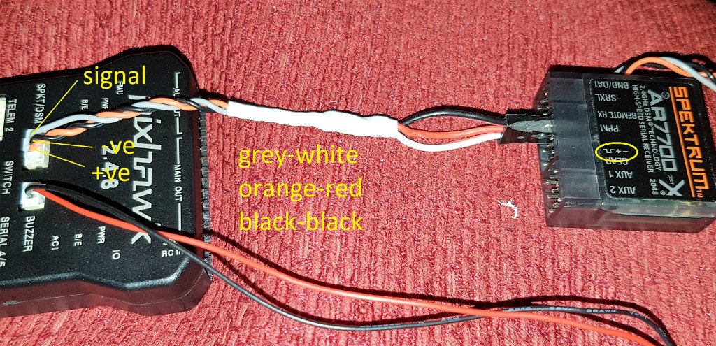
An omission on Pixhawk.org and here is that the spektrum port pinout is not included with all the other ports on the Pixhawk page. The reason it is important to document it is that that port is inconsistent with the pinout of every other port on the Pixhawk. All the pinouts on the Pixhawk are consistent with vcc left and ground right most pin in the df13’s but the Spektrum port does not follow that convention. In the same orientation it’s pinout is left vcc, middle gnd, signal right. This has caused a lot of confusion on the Internet.
Can you add links to the pages that you think need updating? The Ardupilot documentation is available for editing at https://github.com/ardupilot/ardupilot_wiki so you could submit your own changes. I’m less certain about the documentation at pixhawk.org.
Yes thank you. I am not sure about the color coding convention because the original colors I am sure where matched to what 3DR used. Since this cable was probably not included with a 3DR Pixhawk sale, I used the common servo cable colors.