Hi Everyone,
I have a Pix32v6 flight controller that comes with a Pix32v5 Mini base board, and I’m trying to read from the two ADC pads that’s exposed. However I’m unable to get valid reads when connecting a test voltage source to either of the ports. The values read always hover around 0V, and doesn’t respond to changes in the voltage.
Researching around, there seems to be some compatibility issues when using a v6 flight controller with a v5 base board. Based on the documents provided by Holybro, the two ADC pads are not marked as incompatible on the mini base board. But if you refer to the full size base board’s documentation, the two ADC ports are listed as incompatible.
There seems to be a potential conflict in the documentation, as I would expect the functionalities between the two to be the same. With only the form factor, and which ports are exposed to the user being the difference between the two. Can anyone verify if this is the case?
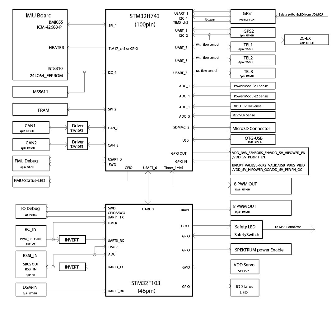
That said, does the Pix32v6 even have an exposed ADC port that I can use? Looking at the block diagram for the FMU processor, there are no general purpose ADC ports exposed.
(There’s a REV/VER sense ADC pin, but what is that for? And is that exposed at all to the user?)
For reference this is the lua script I’ve been using to read the output:
I tried reading from the following pins 4, 5, 8, 14, 18, 103, all except 103 yielded ~0 V regardless of the applied voltage.
(103 is the RSSI pin, and that’s another story)
local sensor_pin = 103
local analog_in = analog:channel()
analog_in:set_pin(sensor_pin)

function update()
    gcs:send_text(0, string.format("Voltage Read: %f V", analog_in:voltage_latest()))
    return update, 5
end

return update()
Thanks for any feedback and / or suggestions