Dear Folks,
is it possible to get an relay’s output 5V on a main pins on the orange cube +? I can not figure out how to set it out. Any solutions?
Ive recently been working on controlling a relay from flight controller with gpio selection of output. I started off buying the suitable relay then the fet to use to enable the gpio to drive enough current to pull the relay closed then i qas messing around with pcb design for the relay and fet and other associated components, then i looked and you can buy a small board all set up with everything already done, they sell them for arduino application. Or there is the hbridge boards from pololu that are designed to drive dc motors which is what i ended up doing in the end
It will be limited to about 25mA on the output pin of the fc.
Incidently some boards like mateks and others include a switchable 9 or 12v with reasonable current designed for vid transmitter power but could easily drive a relay with no issues
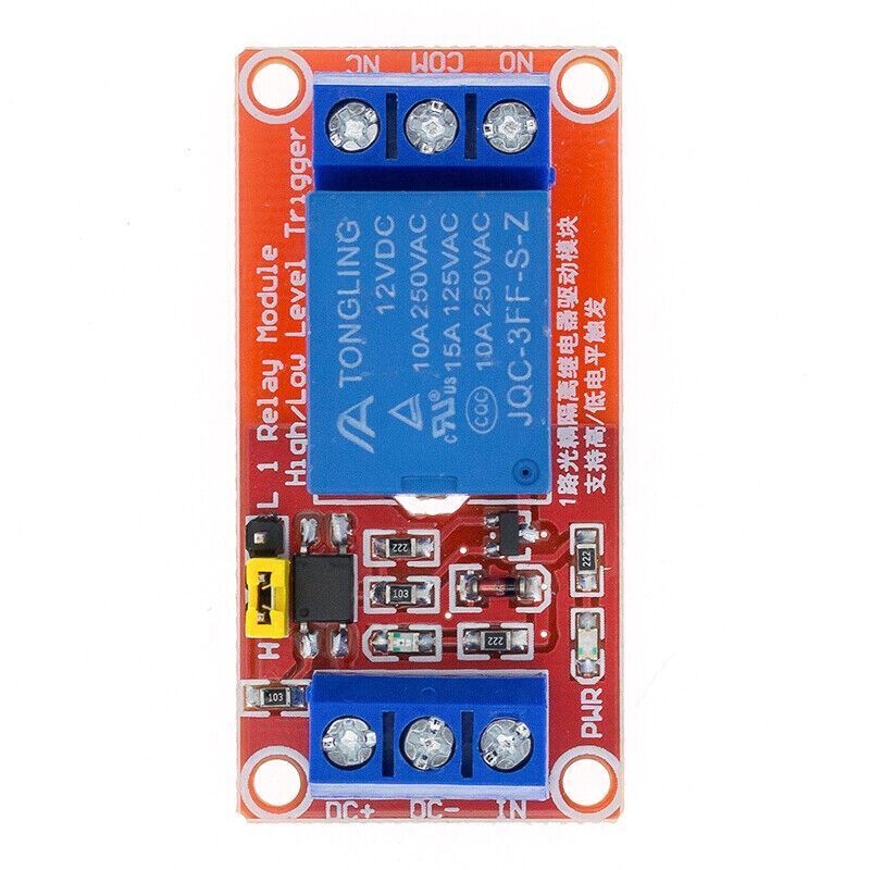
just buy a 5v isolated relay module with high input like these, dont get the blue pcb version as they are input low to switch the relay.
My problem is that I try to trigger bigger relay that is to be raised by 3-12V but immediately after I turn on the relay on AUX1 I have just 2.2-2.5V that is not enough. That is why I look for other options. I read that main out can deliver 5V so even if it collapses a little I think it should be enough to trigger my relay.
Can you share the settings how to set for example MainOut 7 to be working as a relay (5V)?
BRD_PWM_VOLT_SEL: Set PWM Out Voltage
This sets the voltage max for PWM output pulses. 0 for 3.3V and 1 for 5V output. On boards with an IOMCU that support this parameter this option only affects the 8 main outputs, not the 6 auxilliary outputs. Using 5V output can help to reduce the impact of ESC noise interference corrupting signals to the ESCs.
3 Likes
Let us know if this works, it will depend on the current draw of your relay coil. You can test it with a current meter if you have one. I think the i/o pin might still only be good for 25mA regardless of 3.3 or 5v setting of parameter
Its only 2.2 -2.5 not 3.3 because the supply is being pulled down by too much load from the relay coil. Ie more than 25mA.
What is it that you want to control with the relay? What is your actual load application
I’m having a similar problem. I’m only getting .3 V on the signal pin. Is this because the coil on my relay is joining too much current?
That sounds more like a floating ground. Check that you have a proper connection to ground.
Are you trying to drive the relay directly from the signal pin? you need a relay board with a driver to run a relay. the blue pcb versions dont work, it has to be the red version with the jumper that lets you select a high signal to activate it.
2 Likes
I have been working on this same issue as well.
I adjusted “BRD_PWM_VOLT_SEL” to give me the 5V output.
However I cannot turn my relays off once activated. even when I don’t have an actual relay, the pin will output the voltage and I cannot turn the pin off.
what relay module are you using?
I’m using some solid state relays on the other end. I simply need a 3.3V to 5V signal coming off of the signal pins. I was also having the same issue as the OP, where at the relay I would read at most 2V. So I switched to the main pins to get 5V.
However the pin (when relays are disconnected) would read 5V and I could not turn the signal pin off
are you trying to pull it up or down to activate the relay?
what relay are you using specifically.
McMaster-Carr this is the relay. Not much data to it.
Pin goes high to activate the relays.
But as noted, even when the relay is disconnected, the pin stays high
Are you really switching an AC load? If not, that would explain bad behavior from the relay itself.
As for testing with an open pin, that could be inconclusive, depending on pull-up resistor state.
could you explain this a little more? Part of the troubleshooting is disconnecting that relay to verify the pin itself is behaving correctly
More accurately, if your parameters are set up incorrectly, you could measure unexpected output based on internal GPIO configuration.
Which output pin are you using? Share your parameters and also answer my question regarding the type of switched load.
The more I read through this topic, the more I think folks are trying to use raw RC out to switch relays, which will never work properly unless the relay is purposely designed to accept RC input (none mentioned in this topic are designed for that).
1 Like
can you post your parameters?