I didn’t configured i am using pre compiled bin file.
also i am getting cpu near no gps
That means the CPU is being loaded and cannot run at 400 Hz (or whatever you have set) loop rate
Then either compile the code or the simplest option is to use I2C or SPI
Which .bin file you used from the linked repository?
I assume you used the I2C_MPU9250 version.
Which pins ESP32 you used for your GPS UART?
Did you read and follow the readme of the used version:
### UART for GPS connection
UART_NUM_0, .rx=GPIO_NUM_3 , .tx=GPIO_NUM_1
UART_NUM_1, .rx=GPIO_NUM_35, .tx=GPIO_NUM_17
The ESP32 can use any GPIO for any UART!
So connect
- GPS TX Pin to ESP32 GPIO PIN 35
- GPS RX Pin to ESP32 GPIO PIN 17 but in this case you have to move a eventually connectet ESC / Motor from this pin to another.
So show all your now used HW connection on the ESP32 and also ALL your used parameters
now I am getting no gps even neo 6m led blinking and indicating it is connecting to stelite but mission planner show no gps and ekf3 not started
its not working can you please share me your firmware bin file with pin connection on my gmail (bhartiaaditya741@gmail.com)so that I can work.
Did you changed now any wiring now.
Please show all our details as requested:
- HW wiring
- All Params
- All Messages from Mission Planer Message Window
I don’t have a ready built .bin for a quadcopter right now as I am not playing with quads.
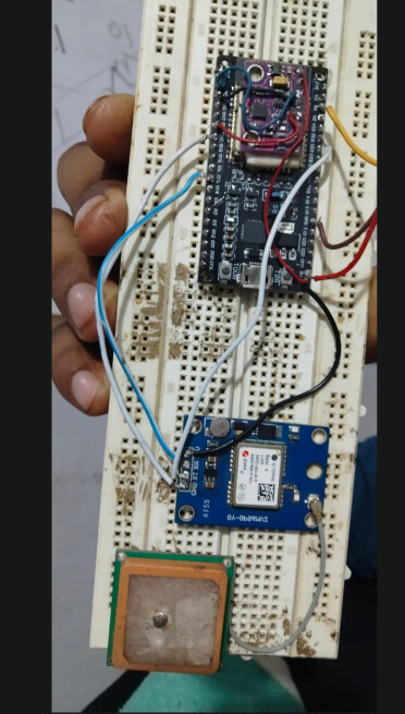
Rightnow i am testing it without frame this is circuit and connection are same as you said according
to linked github repository
Your picture has low quality and is not showing all ends of all wires.
So write down as a list all connection of the ESP32 and there corresponding endpoints
MPU9250 (I2C Bus):
VCC → 3.3V
GND → GND
SDA → GPIO 21
SCL → GPIO 22
GPS Module (UART):
VCC → 5V
GND → GND
TX → GPIO 35 (ESP32 RX)
RX → GPIO 17 (ESP32 TX)
Have you tried using UART0 for GPS anyway even though it is the debug UART? You may have to disconnect the GPS during flashing the ESP.
@StrikeEagle UART0 is fixed connected to the USB Serial converter on the ESP32 Module so it cannot be used for other signals.
@Ab_create are all your connection are good soldered. Your picture is mirrored and show differences to your list. From the picture you also connected the GY-91 Vcc pin via a red line to the first pin of the left row on ESP32 module which is 5V. Is the black wire from the GPS module also connected to this pin? And are the white cable on GPS module a seperated?
And also still your PARAMS and messages are missing.
Yeah I know but still thought it might be good to try since the readme also lists UART0.
The readme list is correct as it is a real UART but only as USB port. The pins are hardwired to the USB Serialconverter.