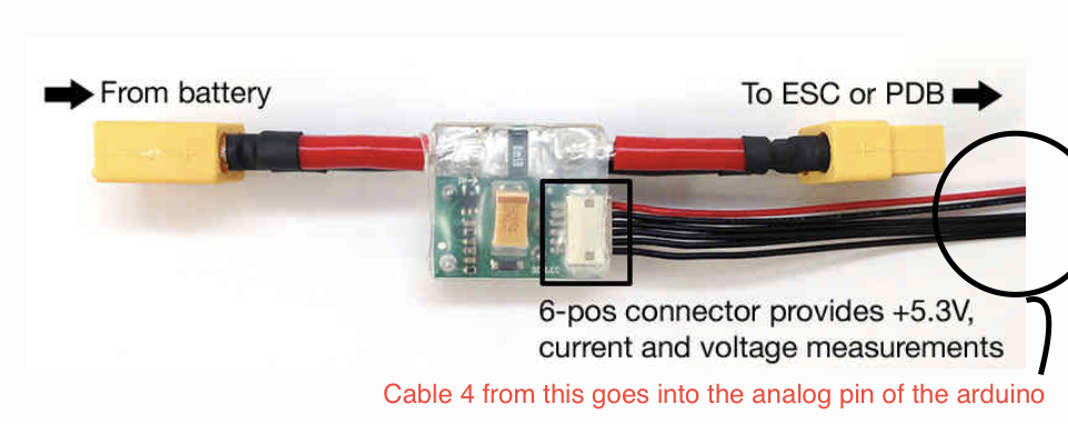
For testing purposes, I’ve my power module connected to regulated power supply and the 6 pin cables is connected to an Arduino Uno (Analog pin), I’m trying to measure voltage value like this, What would be the code to convert the analog value (ranging from 0-1023) to a voltage?
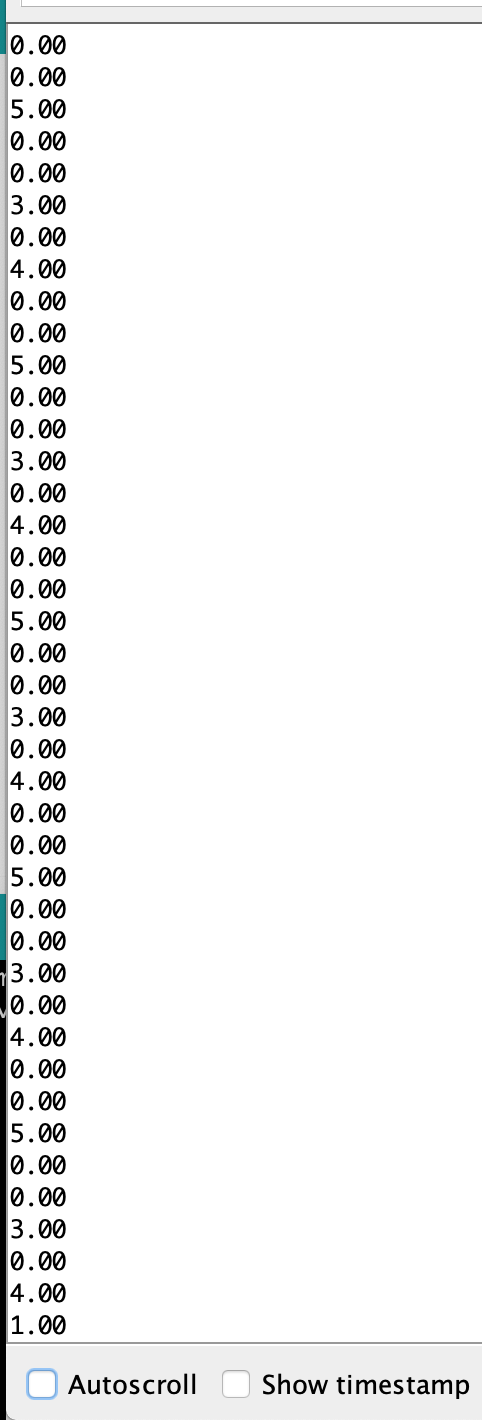
Also the analog value I’m getting is scattered all over the place for a stable voltage, does anyone know’s what’s going on?
This should work if voltage is put on A0. Be sure you don’t have a voltage higher than 5V, though. Might fry Arduino:
float voltage = 0;
void setup() {
}
void loop() {
voltage = analogRead(A0) * 0.004882814; //convert the analog reading, which varies from 0 to 1023, back to a voltage value from 0-5 volts
//or could use voltage = analogRead(A0) * 5.0/1023.;
Also, I have an intuition that it’s giving out a lot of noise, are you aware how does the software filter out that data? Where could I find that firmware?
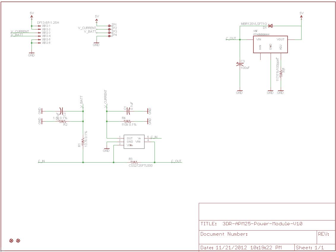
Well, I have never looked at those pins. I found the schematic for the power module (see attached). It does seem that pin 4 should be the battery voltage. You aren’t on pin 3 by accident are you? It is the output of a current sensor (which is not give a part number unfortunately) and I would expect it to be quite noisy. The input on the Pixhawk controller that reads that signal has filtering for that purpose. But, pin 4 does look like you should see the battery voltage. Have you just measured it with a volt meter or better yet put an oscilloscope on it? I will look at mine sometime but I can’t right now.
Yes, you need a ground between the power module and the arduino. Ground is what the voltage is meassured against. Without it you will never get meaningful values.
Both pins 5 and 6 are GND, just as pins 1 and 2 are 5V VCC. Just meassure them with a multimeter to be sure.