The following was a blog posted to DIY Drones in 2013. I’ve moved it here to ensure it remains part of the Ardupilot community, should DIY Drones be discontinued in light of 3DR’s recent push towards commercial markets.
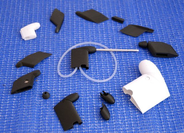
After searching and not finding any neat or affordable commercial solutions, I decided to design my own pitot tube mount. The design went through many iterations in order to optimise it for 3D printing. I wanted it to be simple, to pop apart if it were to catch on something or for transport, and for it to be easy to mount into an airframe. The final design comprises of two parts that clip together, with a seam at 45°. The shape is based on a NACA0025 airfoil, which should minimise drag. I’ve put together some basic instructions on how to mount it below.
Firstly, you need to choose a location that is free from obstructions that could cause turbulent airflow, and therefore effect your airspeed readings. Mount it as far forward as possible, so that the tip of the pitot tube will be in clean airflow. You will also have to consider where you will mount the pressure sensor, and how you will run the air tubes to it.
This examples shows how to mount the pitot tube into the FX-61 Phantom.
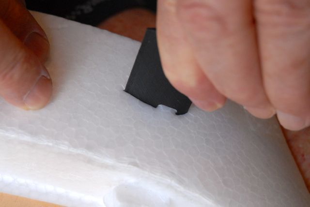
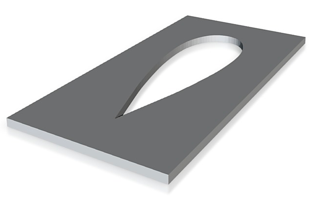
Use the bottom half to mark the foam you’re mounting it into. Alternatively, you can use the cutout template that is included in the Thingiverse file pack, or purchased separately from Shapeways. It’s a flexible 1mm plate that can be moulded around airfoils and fuselages, and held in place using masking tape.
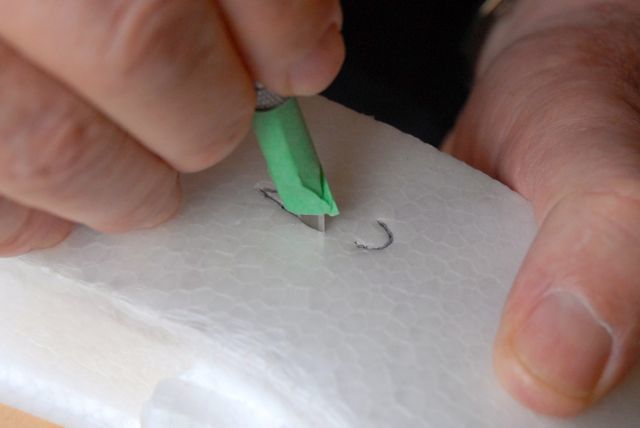
I’ve marked the imprint with a black pen to make it easier to see. Next, use tape to make a depth indicator on a sharp knife. My suggestion is to make the depth around 10mm.
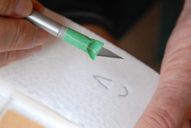
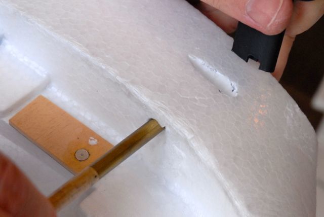
Use the knife to cut around the perimeter to the depth of the tape.
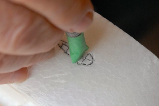
Make additional cuts though the piece of foam that is to be removed. I’ve marked these cuts with a black pen.
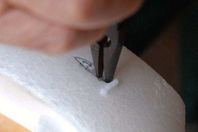
Use needle nosed pliers or a similar tool to pull out the foam.
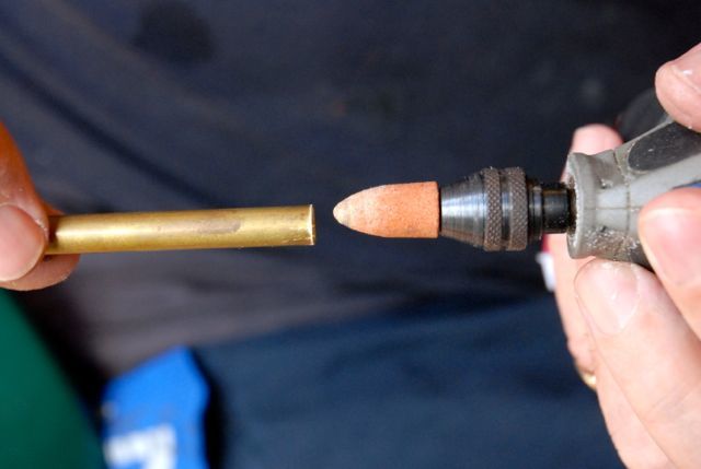
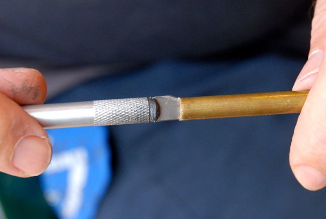
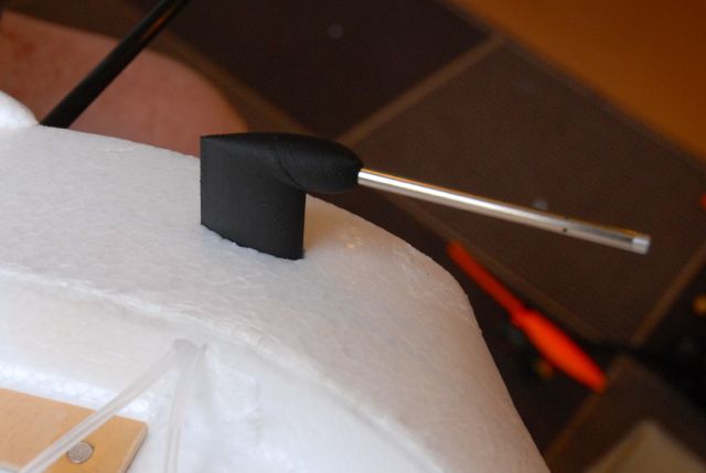
Sharpen the end of a length of metal tube. The best tool to use for this is a dremel, but you can also use an exacto blade by twisting it as shown in the picture if needs be (this will destroy the blade, so use a spare). You want the tube to be at least 7mm in diameter. I was using 8mm brass tube.
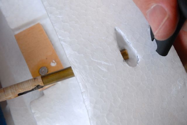
Carefully line up the tube to the hole you have cut out, and twist it back a forth while pushing to cut a hole.
If you’ve got it right, the tube will pop through at the bottom of your cutout.
Feed the tubes through the hole, and through the bottom half of the pitot tube mount. Connect them to the metal tube supplied with the 3DR airspeed sensor, making sure you take note of which tube is connected to the dynamic port (straight) and which is connected to the static (angled). The dynamic port connects to the top inlet on the pressure sensor, the static to the bottom. Thread the top part of the pitot tube mount over the from of the metal tube, and push it into the bottom part of the mount until it clicks. If you choose to, you can glue the two pieces together, but it should sit firm enough that glue isn’t necessary.
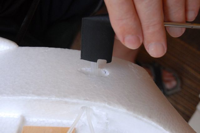
Push the whole assembly back into the foam, while pulling on the air tubes to ensure they don’t catch… Check that the metal tube is parallel with the wing and vertical stabiliser. If it’s off, move the mount around in the foam until it’s right. Any deviation will cause an error in airspeed reading. When you’re happy with how it’s sitting, use glue to fix it into the airframe.
STL and original 3dm (Rhino 3d) files can be found on Thingiverse:
Original ‘clip’ style design
(make sure you print it with the parts rotated 45° so that the seams between parts are level with the print bed)
Screw on design
(easier to print with PLA)
These were previously released under a CC-SA-NC licence, but have been re-released under a GNU - GPL licence. Depending on when or where you downloaded the files, you are free to choose the licence that suits you best. I will also be migrating away from Thingiverse once I have found a suitable alternative, and will update this post accordingly.
These are particularly difficult parts to print due to the necessity for tight tolerances, and variability between different 3D printers. If you don’t have access to a printer, or are having trouble printing them, I’ve also made them available via Shapeways:

