Hello to the mindhive and thank you in advance for any assistance and my apologizes for the long explanation.
This particullar frame has me wondering like crazy (also scared)and reviewing logs and other items before i actually fly it. Came with a broken wookong and an Emlid Edge to replace it with.
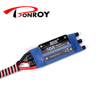
Aerovioniks Skyjib, Dual Sky XM5015TE-6 motors, DYS 50AMP SimonK ESC, Aeronaut 16x6 light proppelers a DX8 radio and 2pcs 6S 8000mah packs.
Build went smoothly as also first couple of flights, to check funstionality. Also did a couple of full discharge strapped tests on which we tested licing it at 50-80% THR to check what will happen with temps and if anything would fail, which nothing did fail so we went to field. First time on land i found that Damping was way to soft and replaced with stiffer as also due to damping and the fact that i had NOT taken ATC FILTER from 20 to 10, all the pid was not correct. Tuned MOT_SPIN_ARM from the point of motors starting to 3 up (spin was at 0.085 and i placed it to 0.088) and MOT_SPIN_MIN i did 7 above that (0.95, its a big frame with really tiny landing gear for its size and easy to flip over) And the problems start:
Since then i have had 1 or even 2 motors stopping during flight (thankfully it did not drop from the sky) and my actions were as follows. Tuned radio to give RC3 from 1050-1950, calibrated radio with FC again, took one by one all ESC and calibrated with this radio setting, checked a large variety of dampening solutions (in case FC is going crazy because of this) but still have the same problem. My questions are as follows:
a) Could MOT_SPIN_ARM and MIN be a problem? maybe i should go 0.1 and 0.15?
b) Could SERVO1-8 be the problem? since they are set to 1100-1900 while my radio is 1050-1950? (it shouldnt be)
c) Could RC_SPEED be the problem? Is it possible that these ESC’s cant properly refresh at 490Hz?
d)Could it simply be the SimonK firmware and the fact that this is a large copter? (i read about some issues of this kind in the past)
I am uploading a log on which it did not actually fly, but we had it hovering and testing motor function and ready to grab and kill motors while testing a little roll, pitch and yaw corrections to actually make it possible to take off and finally tune, but one motor stopped again (motor3). Any ideas?
After More investigation (since this was not a complete build from me) i was able to narrow down the speedos, only to find that manufacturer states as BEC:Opto! This means i need to make a common ground and need to power the ESC’s from a BEC. (atleast this is ,how it was in the past on ardupilot and i think it still is) I need to open them up one by one replace all BEC cables to include also the red wire. Does anyone know atleast if i can properly power the rail of the Edge so i can power up properly the OPTO ESC and finally solve all issues?
Opto ESC’s only need the 2 wires, Gnd and Signal.
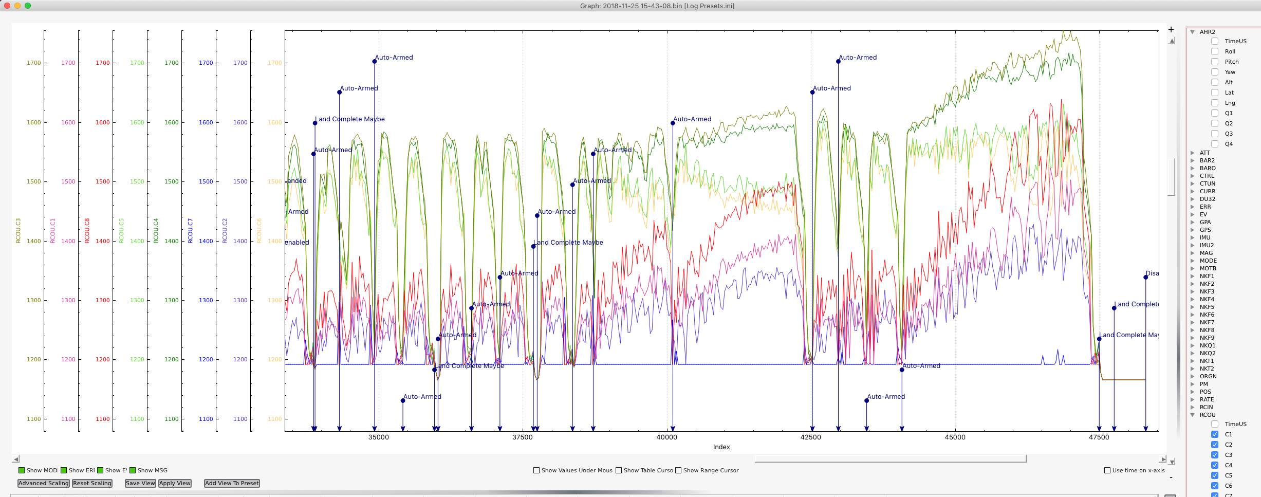
Having a quick look at the PWM outputs to motors it seems you have something seriously wrong with your frame or motor/props.
Consider that unless you are fighting strong winds the PWM outputs should be roughly the same.
Is the Octo balanced about its centre point?
Are all the motors/props level and in the same plane?
RC7 isn’t even spinning up beyond idle??
Hello Mike and thank you for your reply.
As per wiki front right is right and going cw from there is left and so on. So yes props are correct or else I would not take off or hover. Frame is flat, motors flat too and tested with a level and also by eyes. Esc calibrated one by one through rx but as I saw on wiki http://ardupilot.org/copter/docs/connect-escs-and-motors.html says that opto like kde…the ones on this are Chinese DYS should be powered by a Bec. Since I noticed the issue when forcing throttle I would suspect that since the don’t have proper power for the opto led they never sync properly and basically the FC compensates we’re it can to level the uav. In the attached log it was help on the ground slowly punching power till I could see an esc rebooting. Also this is wierd part, they reboot. And if you disarm and arm again they work till they reboot/desync (to the point on not working until armed again) I think most of the issues seen here might be because of poor power to the OPTO
Would it even hover, and specially with 7 or 6 motors if directions we’re wrong?
Edit: I contacted DYS to verify if they need 5v or not but I should mention that they sell them as simonK multirotor each and from the factory they come with a 3 wire servo lead, I suspect power is needed for them to run stable.
The 5v should NOT be needed to the ESC - it’s an output to run other equipment off, NOT to power the ESC electronics !!
So what you should do is disconnect the 5v wire from all ESC’s except one, and have the one remaining 5v wire power the servo bus on the pixhawk, in case you plug in any servos that need power.
Definitely DO NOT have all the ESC 5v wires connected together or to any other BEC - they will fight with each other and potentially overheat or cause damage!
EDIT: In that link you provided it’s really about SPECIFIC ESCs, the KDEXF-UAS and KDEF-UASHV. These are atypical from what I understand, and every other opto ESC on earth doesn’t need a 5v source.
OK, I give up - just doing a quick google it looks like some of the DYS ESCs also need 5v power to run the opto. That’s news to me, however I’ve probably got limited experience with ESCs. Although those ones should also have the suitable wiring already attached from the factory - I cant imagine you’d need to disassemble the ESC protective covering to add the 5v wire.
I’d continue investigating the issues that mboland pointed out.
True “opto” esc’s need to be fed 5V.
It’s unfortunate that many manufacturers incorrectly use the term to indicate an esc without a Bec, rather than to indicate an esc with an opto-isolation circuit.
If these are a true “opto” esc then they most definitely need to be provided 5V.
you might be correct, but in this case i have an octa that landed in my hand with 8pcs of “OPTO” esc’s that no one is sure if they are true opto or not. Not even the factory yet. spoke with them direct and they are investigating.
I may be wrong but always thought that If you have a ohm meter you can find out. Pretty sure that if the power ground and signal ground ate common- it is not t true opto.
@mboland@xfacta@james_pattison@JoeBreznai
Thank you all for your time and reply, responce from DYS was as follows:
DYS: MB30050 is OPTO version and without the BEC
ME:all opto is without BEC. but some opto can supply power to ESC from main battery and some need seperate 5v. which one is this? do i need to give 5v?
DYS: yes, you need give 5V
I suppose this clarifies it: fingers crossed.
Also by taking them apart to start installing new wires (all three) i found that the main issue ESC had one of its caps leg broken (it was as it it was cut by clippers)
Hope that as soon as all is ready and powered up it will not burst into flames!
Latest Update:
Late night here and not possible to actually run it and see what happens but i will say the following:
A) all esc now have normal servo lead with 3 wires connected to pixhawk and a BEC on the rail of pixhawk to power them.
B) all capacitors since i found the one that was cut have been replaced with new, instead of 330μf 105C low ESR to 470μf
C) i simply plugged a battery holding my…and so far so good, no flames and all motors started
D) sounds smoother on the feeling of throttle and linear.
Tomorrow i will run a strapped test to see what has changed if PWM outputs are becoming more level and if it feels different in general taking it through its paces. And yes, check if any ESC will reset again or not.
Once again, thank you to all for the assistance and i will update this section with more info that can probably assist another person in the future that finds him self in my position.
@mboland
Today i tested the “correct” DYS wiring theory and fixed ESC capacitors. Run a strapped test and things seem different. you can see log here https://plot.dron.ee/nryl
EVEN though PWM are not the same, THR feeling is smoother and linear and while it was strapped with not a level horizon the whole thing did not fail. I tested with empty packs (this log) and also run a full set of pack with throttle 50-75% to see if i will have motor temps and ESC failures. For now everything runs without failure and motor/esc temps dont exceed 35-40c so i have a feeling that this is ok now.
PWM is still off and i will check again frame flexibility as also having it strapped not perfect level and occasionaly forcing roll and pitch to check what motors will do, probably did not help. As soon as flown and tuned i will give an update that might also help other people in the future.
Thanks for clarifying James - yes I see what you’re saying, and I’ve always understood what “opto-isolated” really means from an electronics viewpoint.
I’m late to the done/ardupilot scene so sometimes I believe what manufacturers say when I shouldn’t.
It seems some of the manufacturers or resellers don’t even know their own product.
It’s crazy that an ESC that’s apparently opto-isolated and requires 5v (plus the usual 0v and PWM) doesn’t come with the required wiring already attached.
Let me explain. Photo above shows how the ESC comes. Copter in my hands came “semi-assembled” and not with 3wire servo leads, but 2. This means the original builder did it on his own.
After trying to find bit by bit, why things did not work (uneven PWM, motors stopping while flying and plenty of other) i came to the point that i took ESC not OFF, but completely apart. From the board markings i tracked the manufacturer, came in contact and from the board number they told me which one it is.
Talking to DYS for info on why does it have 3 wire leads and if it actually needs power, if its “opto” or true opto was a lengthy task. In the end they gave an official reply. Even though getting confirmed info was hard, i must say that atleast on the picture, the ESC comes with proper wiring.
I redid the wiring on all 8 ESC and found also that one Capacitor leg was broken, and since i was worried and cost was minor i replaced all 16caps on the ESC with 25V 470μf instead on the 330, once more using low ESR caps. This was for sure a learning experience for me and i thank you all for your input.
Today its take off testing and if all goes well, also autotune.
To all the people in this thread, in case its of interest and also for assistance on people with similar issues in the future.
As it seems there are “OPTO” ESC’s that need power, but even without power and work (not properly, but they do) with results such as mine during flights. Huge Differences on RCout, Motors stopping in the air and ESC rebooting and many more.
Finally today i was able to run a 0.75 Autotune on Roll and simply copy the numbers on Pitch so that i could have enough time to run an autotune on YAW also, so that the whole thing could be flyable. I landed on AltHold which is not the best way for “first” time flights, but i wanted to make sure i will have the PID saved and landing was pretty good(for only one axis tuned). Yaw Autotune log shows that PID is not perfect but PWM are close and leveled and PID overshoots by a little but tuning P down a bit it will sort things out. https://plot.dron.ee/RNQY here is the log for anyone interested. Due to the fact that rig is pretty big and that Vibes are within acceptable levels i had activated Ground Effect compensation since this Rig created havoc of air close to the ground. Any comments are always welcome. (I do see the noise on the desP vs P and same on roll but I will test manually to lower P from 0.335 to 0.325 just to check if it’s high P or high D)