3.4.5 Enhanced Camera Trigger Precision - Limited to 200 ms?

Hi all,

In a similar nature to another post, I’m exploring the potential of using the Swift Navigation Piksi RTK GPS to eliminate the need for ground control points. I’ve run into a few issues however with obtaining a precise GPS timestamp of when my camera shutter is triggering.

My hexacopter setup includes a Seagull UAV #MAP2 that enables the Pixhawk to directly trigger a Sony A6000 camera, along with a Seagull hot shoe connector to precisely log when the shutter triggers. GPS1 is a uBlox NEO-M8N, while the role of GPS2 is fulfilled by the Piksi, but only in a logging capacity.

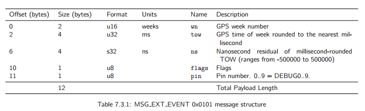
The initial thought was to timestamp when the shutter triggered using the Piksi, which has the ability to log external events. However, the Python scripts that should enable a user to parse out the relevant information from the Pixhawk’s dataflash logs were never fully developed by Swift Navigation. Despite some limited assistance from SwiftNav, I unfortunately haven’t been able to get these scripts working.

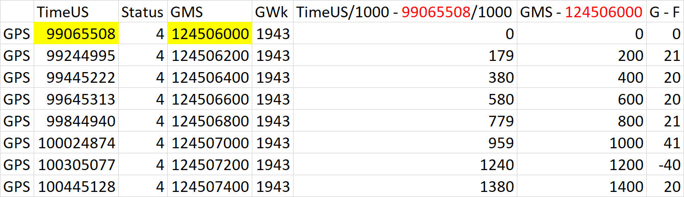
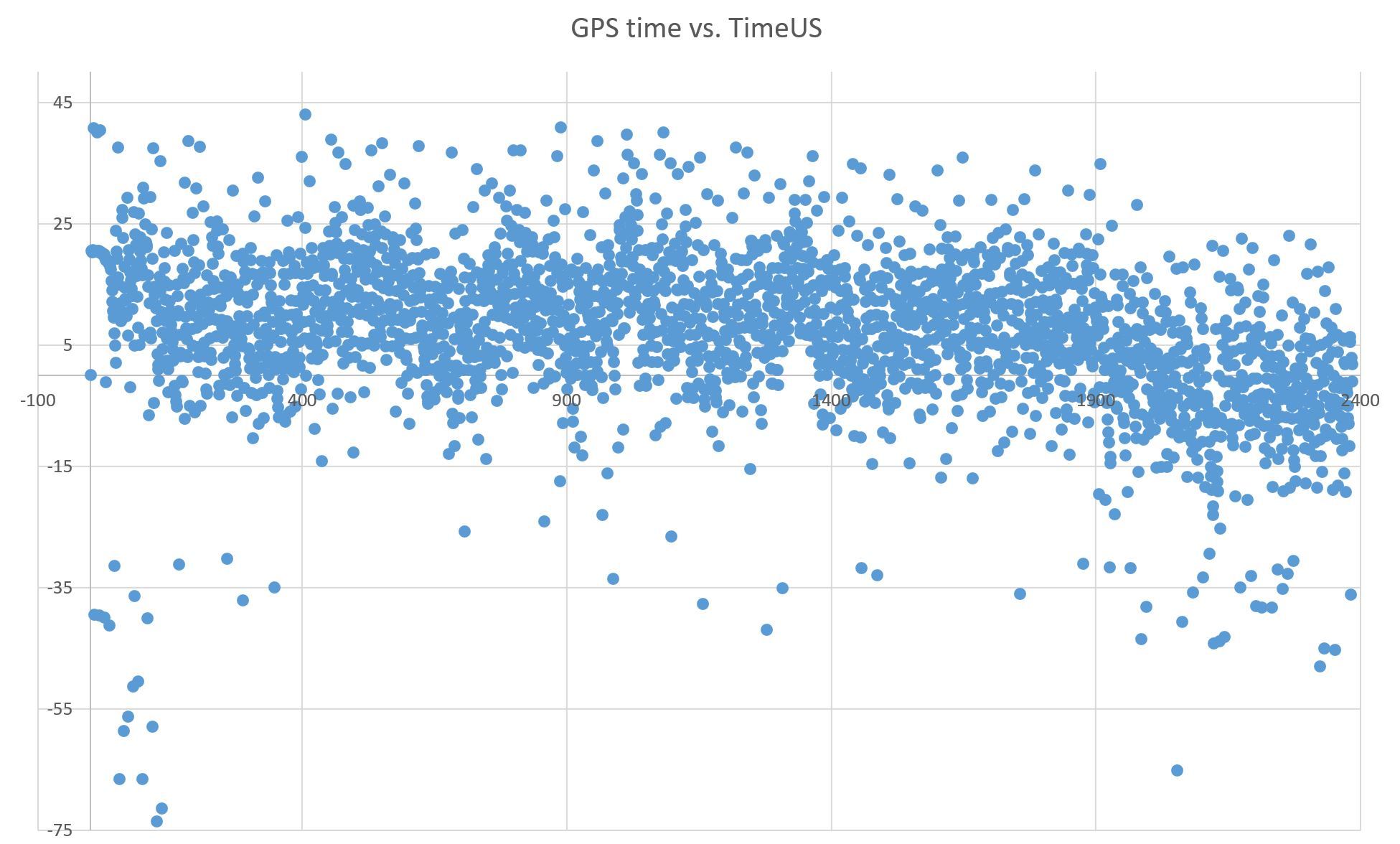
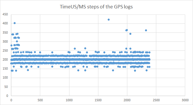
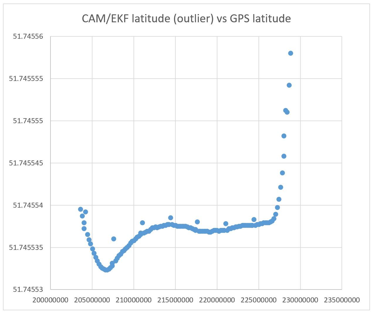
This led me enhanced camera trigger. I envisioned it could be used to obtain a precise GPS timestamp of the shutter event that could be employed (i.e. interpolated) later during the post-processing of the Piksi RINEX data. With my hot shoe connected to AUX5 (CAM_FEEDBACK_PIN = 54 & CAM_FEEDBACK_POL = 0), the camera trigger logging has done a great job of providing reliable CAM messages. The issue however is that the precision of the GPSTime in the CAM messages appears to be limited to 200 ms (0.2 s). Given even modest flight speeds of 5 m/s, this represents an uncertainty of 1 m, which is understandably much too coarse of a location. I’ve observed in the data flash logs that GPS messages are also limited to the same millisecond precision, so I wonder if this is where the issues stems from.

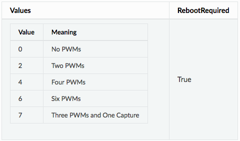
I am also curious if the “fast capture” AUX4 (pin 53) could be a possible solution. In the CAM_FEEDBACK_PIN description, AUX4 is said to be able to provide up to 1 microsecond precision, but I have not been able to produce any CAM messages with my hot shoe connected to this pin as of yet. I am also unsure as to how this timestamp is calculated.

I’d appreciate any help or suggestions that could be offered! While the general consensus appears to be to simply “buy an Emlid Reach”, I’d like to at least attempt to make use of the investment we made (regrettably) in the Piksi.

Cheers,
Adam

Hello, I’am also interest to your goal.

I guess Pin53 is not working for CAM message because probably you got BRD_PWM_CNT= 4 so
50 = RC9
51 = RC10
52 = RC11
53 = RC12
54 = Aux 5
55 = Aux 6

Try with BRD_PWM_CNT= 2
Pin 52 & 53 become AUX3 & AUX4

@adam.g the CAM messages are tagged with the most recently received GPS iTOW (intenal time of week). Unfortunately for high percision GPS syncing you need more hardware connected. The GPS information is only parsed at 50Hz, which can lead to a 20ms jitter of the timing information. To correct for this we need to support the PPS signal and use that with a feedback pin. I have hardware capable of this now and it’s on my agenda but it isn’t a high priority yet.

The TimeUS field could be used as a workaround for now, the camera will only be trigged on receiving a new GPS message, which means that the offset from GPS to TimeUS can be determined by the TRIG message. You then know what the offset is when you get to processing a CAM message. This is a bit of a pain though, and I suspect you will be happier with the python scripts if you can get them to work.

This is a bit of a rushed answer, if it doesn’t make sense please let me know and I’ll try to explain in a bit more detail.

I am also interested in this. Quite a while back I made some tests regarding the timing jitter and the difference between TimeUS (TimeMS) and GMS of M8N GPS.

I made a quick test based on a recent log of a short flight with am M8T. This is the first rows of the extracted GPS data:

The idea was to compare the 200ms time steps of the GMS data with the corresponding time steps of TimeUS.

In this test the difference was between +43 and -74ms:

I my previous tests the differences were even higher. Same as here there were trends over time and there were visible differences depending if SBAS sats were used or not. So I guess the timing differences are processing issues of the M8 GPS.

So the question is if TimeUS can really be used as a workaround if the offset is not stable.

These are the TimeUS (converted to TimeMS) steps of the GPS entries. In most cases it is either +20ms or -20ms…

It’s not really expected to be stable unfortunately, it is still a work around that gets you closer then a 200ms step size, but I definitely agree it’s still noisy.

Just to make a couple of things clear, you aren’t seeing a GPS position in the CAM/TRIG messages you are seeing the EKF position. The altitude_gps entry is the GPS altitude, but the rest is all from the EKF. You also need to be aware that a GPS unit typically has an internal lag on propagating changes out (IE on ublox this tends to be 220ms or 120 ms depending on what hardware generation you have).

@WickedShell

I ran some further tests and have some questions…

I compared CAM/NKF latitude vs. GPS latitude. If I have no bugs in my calculations they can differ by 30cm in some cases in my log. No matter if the internal lag is compensated or not.

So to get more precise coordinates for georeferencing the coordinates of the GPS messages should be used instead of the CAM message coordinates. Is this correct? For sure the internal lag has to be taken into account and some interpolation is required as well.

Are there differences between RTK (M8P) and PPK (M8T) regarding the GPS internal lag and the coordinates reported in the CAM messages?

You mentioned that the internal lag [quote=“WickedShell, post:6, topic:16798”]
tends to be 220ms or 120 ms depending on what hardware generation you have
[/quote]

220ms is the default setting in AC. What do you meen by hardware generation - M8 (120ms) and the Lea6 (220ms)?

Since there is noise, timing jitter and also sometimes missing GPS messages, I am wondering what might be the best approach to retrieve the best possible coordinates for a specific TimeUS/GPSTime. This is especially important for PPK. For example when M8T raw data is recorded and post-processed the only option to correlate the processed data with the CAM logs is GPSTime. So my question is: what is more relieable - the TimeUS or the GPSTime? I guess the TimeUS. So GPSTime should be adjusted to account for the noise/jitter?

Sorry for bothering you with so many questions!
Thanks a lot in advance!
Thorsten

Hi,

I am very interested in this too. My little experiment so far using Arduplane 3.7.1 and hotshoe on NEX 5, CAM_FEEDBACK_PIN=52 with an ublox M8N:

  1. using MP geotagging CAM_messages Agisoft Photoscan reports
    X error (m) = 4.53323
    Y error (m) = 1.81875
    Z error (m) = 0.440147
    XY error (m) = 4.88447
    Total error (m) = 4.90426

  2. using linear interpolation on the GPS data from the log results in:
    X error (m) = 2.28678
    Y error (m) = 0.905592
    Z error (m) = 0.982533
    XY error (m) = 2.45957
    Total error (m)= 2.64856

  3. using linear interpolation and 220ms offset on the GPS data results in:
    X error (m) = 0.440397
    Y error (m) = 0.367895
    Z error (m) = 1.04474
    XY error (m) = 0.573843
    Total error (m)= 1.19196

  4. same as 3) but with camera x-offset:
    X error (m) = 0.265161
    Y error (m) = 0.295929
    Z error (m) = 1.04285
    XY error (m) = 0.397347
    Total error (m) = 1.11598
    Surprisingly the error had a minimum at the correct x=-0.39 offset value, -0.38 or -0.40 and error was bigger.

  5. same as 4) but with camera z=0.7 offset:
    X error (m) = 0.254608
    Y error (m) = 0.286169
    Z error (m) = 1.04423
    XY error (m) = 0.383038
    Total error (m) = 1.11227
    Z=0.7 resulted in the minimum on total error, but z-error went up.

Edit: update
Everything the same as in 4) except altitude values recalculated using baro height
X error (m) = 0.265181
Y error (m) = 0.29574
Z error (m) = 0.409101 (was 1.04285)
XY error (m) = 0.397219
Total error (m) = 0.570217 (was 1.11598)

Hi all,

Thank you for the valuable feedback. It’s certainly generated some interesting discussions!

@lucamax Valuable reminder about BRD_PWN_CNT =4! As I require a minimum of three PWM outputs (tilt/roll/camera trigger) I will try to change to BRD_PWN_CNT = 7. This value should provide three PWMs and one capture.

@WickedShell I appreciate the detailed explanation regarding how CAM messages are generated and their associated uncertainties. It seems that my best option may to redouble my efforts at getting the Piksi Python scripts working. According to the Swift Navigation Binary Protocol (SBP) documentation, the external event is precise to the nearest rounded millisecond. The Piksi datasheet states that position/velocity/time solutions are calculated at 10 Hz, so I wonder if this means that the Piksi is producing additional time solutions on the fly.

A typical external event trigger message including a GPS TOW to the nearest millisecond is shown below. I am unsure of the internal lag inherent to the Piksi, and to what extent it could be influencing the accuracy of the timestamp. This may be a good question for SwiftNav. However, if the time is correct, then could it not be used to interpolate a precise and accurate location from the PPP post-processed RINEX data? I unfortunately don’t have a great deal of experience with interpolating positional data as of yet, so I’m not clear on the feasibility of this idea.

{"data": {"sender": 10878, "msg_type": 257, "wn": 1945, "tow": 513482342, "crc": 27012, "length": 12, "flags": 0, "pin": 0, "ns": 364413, "preamble": 85, "payload": "mQdmHpsefY8FAAAA"}, "time": "2017-04-21T23:41:08.845000"}

@Thorsten Thanks for all the great information on the TimeUS and GMS differences! It’s interesting to see just how difficult it is to determine a suitable offset, and how much the noise/jitter can influence this value.

@ultrafuge Great experiment! I’m keen to learn more about it and impressed at how much the error was reduced by interpolating and including an time offset. For the x & z offsets, I am assuming these refer to the horizontal and vertical offsets between your camera and GPS? Very strange that your Z error would increase when accounting for the vertical offset. Did you also have ground control points to compare your results with? Ideally I’d like to conduct a similar test in the near future.

Cheers,
Adam

Yes, basically the GPS is 39 cm ‘behind’ the lens (x=-0.39), y=0 and z should be a few cm.

Not really accounting for vertical offset, because the physical z-offset is less than 5 cm, I was just trying to get the ‘total error’ to the minimum by playing with the x, y and z offsets. This ‘total error’ minimum happened at (x=-0.39, y=0,) z=70 cm and the z-error increased by only 1.38 cm - confusing, especially considerung, that any deviation from the physical correct x <> -0,39 or y <> 0 made the result worse.
200ms or 240ms time offset was worse than 220ms.
Case 1) uses baro altitudes, all other data uses GPS-altitude.

Sorry, no GCPs.

I expect to get much better results with the emlid reach, but I need to get better antennas.

An alternative (PPK): http://rtkexplorer.com/how-to/hardware-projects/

Hi everyone,

I am very happy to find this debate (thanks to adam.g) and
that some people are also struggling with this time mess:)

I read all posts and have some questions. I take M8N and connect it
to computer. I close all NMEA messages, but the one with time and
raies BAUDRATE to 115200. What accuracy should I expect? Would
it be stable or very noisy? Is there a lag of 220 ms? Is there any test/datasheat/answer
from ublox about this lag?

And also another set of questions. The M8N timepulse should be accurate
way below microsecond. So the combination of timepulse, nmea time
and microcontroller would give the result? Microcontroller would
parse nmea time message, timepulse and camera trigger would be used as interrupt.
Would that go?

Far more comments have come in since last night, and far more then I have time to respond to at the moment!

@Thorsten I’m trying to understand your graph, but I’m not following what I’m being shown.

ArduPilot is already doing Lag compensation for you on the solution output by the EKF. Depending upon your flight speed 30cm is quite reasonable (even tiny) for the difference between EKF vs GPS distance) assuming that you are using a hot shoe to get feedback when the camera takes a photo. This can easily be 0.1 seconds (or worse) from the moment you command taking a photo (which always aligns with a new GPS update at the moment).

I’m afraid I can’t recall off hand if the M8P came out different then the M8T. At the moment our level of detection is only telling us major versions (ublox 5/6/7/8). If you don’t set the parameter value we will select the GPS_DELAY_MS parameter we will attempt to select the best value for a u-blox driver, while any other GPS will just use 0.2 seconds. So what I meant by hardware generation is that we use 0.12 seconds for a ublox 7 or 8, and any other ublox we use 0.22 seconds.

GPSTime is the iTOW, it’s timestamps shouldn’t be adjusted however you are seeing the timestamp when we actually log a GPS message which does give you a sense of when that actually is arriving.

@ultrafuge Biggest surprise is that 1) should have been as good (or better) then 3 in theory (at least without using an RTK GPS)…

@adam.g BRD_PWM_CNT must be a multiple of 2, 7 won’t work, you should see an error print out on the debug console if you had a debug cable attatched.

ArduPilot handles 10Hz messages quite well, and I know that the SBP2 driver that just went in is setup/tested that way. @njoubert whats the requested update rate of the SBP driver?

The external event pin is exactly what you want to be using for this! Ideally you would either be working on an RTK data set, or PPK it first, then you can do exactly the interpolation as you were thinking. You will get better results if you know the internal lag, but this is the best path forward. You just need to manage the interpolation. (Hint: avoid floats for processing, doubles might be okay, but absolutely avoid using a float anywhere in the interpolation :slight_smile: )

We should note that the numbers from @ultrafuge’s test are the reconstruction errors, and don’t actually reflect on the real world (absolute) accuracies, however reducing reconstruction error is always good (although sometimes this can actually just be an excacerbated toilet bowl effect, I don’t think that’s what you would see with the corrections that were done.

@jero If you are going to do an external solution use the PPS pin. Once we support that in ArduPilot that will be even better but, we aren’t there yet. For the record the PPS timing will actually change depending upon hardware version/settings, so it’s not the perfect solution, but it is much, much better and still the one we should be chasing.

Thank you VERY much for all the infos !
My little experiment is for sure not claiming the absolute truth, but the results are derived from calculations with the log data. I will try another data set in the next weeks.
Doing some calculations with baro altitude I get these results:
Everything the same as in 4) from post #8 except altitude values
X error (m) = 0.265181
Y error (m) = 0.29574
Z error (m) = 0.409101 (was 1.04285)
XY error (m) = 0.397219
Total error (m) = 0.570217 (was 1.11598)

Hi folks!

Yup, the latest SBP2 driver for the Piksi Multi GPS runs quite comfortably at 10Hz. We ship Multi with a 10Hz update rate by default.

@adam.g Nice to meet you! I’m here at Swift, working on our UAV drivers. Are you using the original Piksi or the new Piksi Multi?

As for the external event trigger: you get even better than millisecond accuracy. When the event pin is triggered, we generate a tag inside our hardware FPGA that’s nanosecond-accurate. The SBP message contains both rounded milliseconds and nanosecond residual. This event trigger is separate from the position solution, so if you want to know the exact position of that event, yes, you have to interpolate. I like the idea of generating a PVT solution for an event trigger - I’ll bring it up with our estimation team.

You also mention the ability to extract GPS data from the Pixhawk driver’s logs. We do have that functionality, I can help you get that up and running if you need that.

I’m also curious how the Reach solves your problem? Ive looked through their docs, and AFAIK all they’ve done is reuse the code I’ve written for SBP to parse their binary protocol for RTK - they’re using the same RTK injection system I originally developed. Seems like the specific thing you need is easier post-processing, is that right? That’s useful feedback for us, so I can prioritize what we work on.

Cheers and thank you!

1 Like

Thanks again everyone for your insightful comments!

@WickedShell, I thought that BRD_PWM_CNT = 7 sounded a bit funny, but the value was listed on the ArduCopter Complete Parameter List (http://ardupilot.org/copter/docs/parameters.html#brd-parameters). Perhaps 7 is a mistake?

Thanks also for the confirmation on using the external event pin and for bringing @njoubert in to the discussion. Hopefully he’ll be able to help us with extracting the data recorded by Piksi from the dataflash logs. Time for me to get reading on post-processing!

@njoubert I appreciate for the additional clarification on the SBP message! I believe Dennis Zollo had created a Python script to perform this interpolation last year, so you may want to check with him. The lack of easy post-processing solution for the Piksi has been an issue for us, and this is why the Reach had been suggested. I believe providing the end-user the ability to interpolate a PVT solution would be a really great idea! I’d also love to get your help with extracting the GPS data, and have sent you a message detailing some of the progress I’ve made.

Cheers,
Adam

@adam.g Your right I missed that one! It’s still in the code :slight_smile: (I have no clue what the actual pin mapping is but, does look useful).

@Thorsten, did you find a way to extract the gps position with the CAM message, and not the position from EKF?

With my tests, while not flying, with a TERSUS RTK GPS and surveying Equipment, I got an average 10 cm (5 cm to 30 cm) difference between the CAM messages and the GPS2 messages extracted just before of after the photo, while not moving the drone (on the ground).
Comparisions between surveying and GPS2 messages is 0.5 to 2 cm in XYZ, no more! Excellent!

Is it a way the CAM message gives the interpolated RTK position, or to give priority to RTK positions?
RTK is 10Hz, whereas IMU with EKF is 400Hz

Hi @pica,

I have not looked much deeper into it and in most cases rely on what @WickedShell wrote:

As this should be the difference between the two GPS, you could use the GPS time to synchronize both. Do you have a dataset (images and dataflash *.log) to share so I could run some tests in Mavis (mavis.bitmapping.de)?

I don’t mean to revive a relatively old topic, but I’m still wondering if the DataFlash Cam event timestamps are still rounded to the nearest 200ms, or if they are logged as the exact time that they happen (assuming the resolution is 1 ms). I’ll be using a hotshoe feedback cable (for Capture) and RTKLIB for post-processing and interpolation, and plane 3.8.4.

Not sure what you mean. Depending on your hardware you can use the standard or the fast port for logging the CAM events. In post #12 WickedShell is talking about 120ms and 220ms delay for ublox.