As i said earlier, The issue i am having is the rover not being able to hit the waypoint, because of the GPS inaccuracy that happens from time to time, and the lidar detecting an obstacle (if you know what i mean). The car won’t reach the waypoint, so i increased the WP_RADIUS so it could hit it earlier, but for some reason it doesn’t work, and the vehicle still wants to go thru the middle of the waypoint. How can I tell the rover to have bigger tolerance for waypoints? Am I setting something wrong?
another thing is the vehicle reacts very late to an obstacle (the obstacle cant just appear, it needs to be static and not moving, because the car will not be able to steer away in time), Is there a setting to make the avoidance reaction less sluggish? and make the reaction time quicker?
Also, There is still noise appearing from time to time, could the sun cause this issue? Pretty unfortunate that ardupilot doesn’t have the circle amount ignorance, that would help a lot!
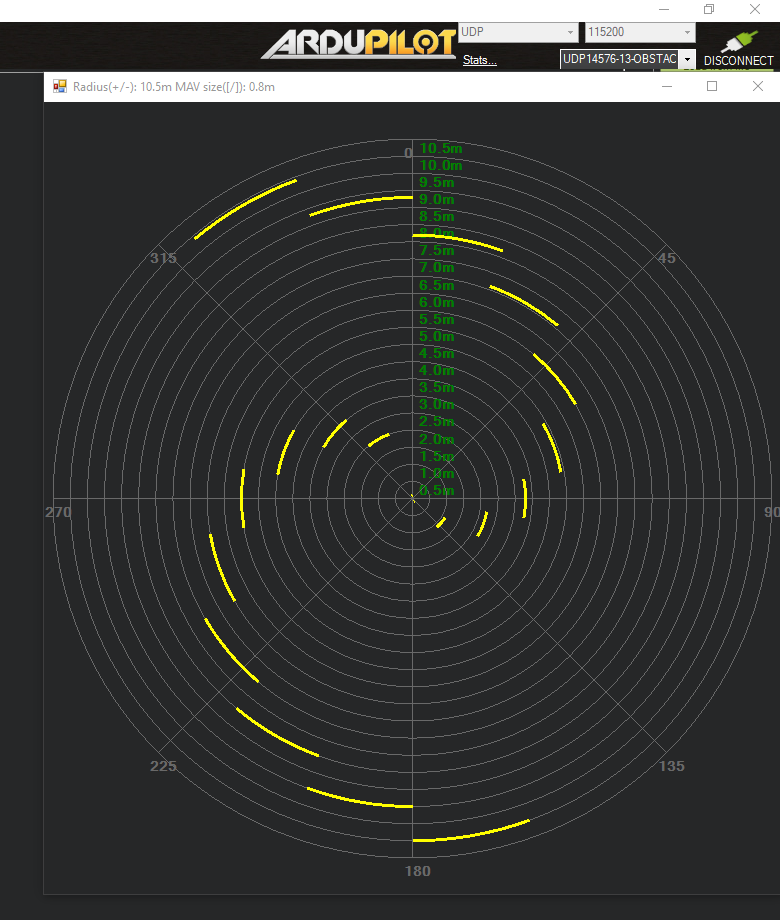
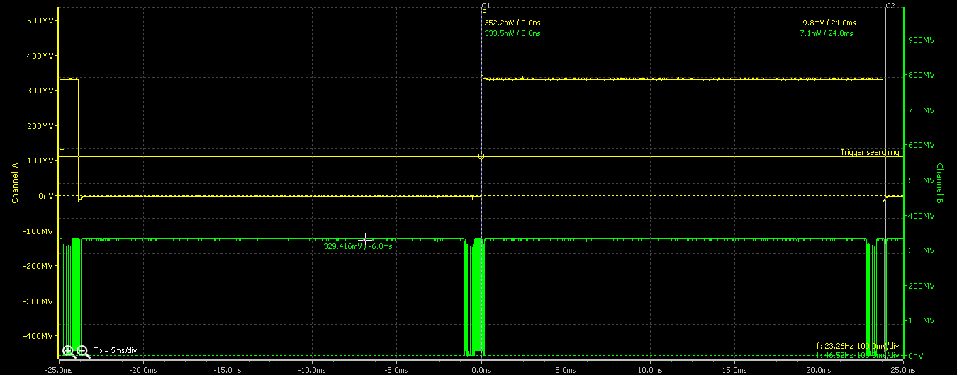
How do you get radar window with those nice yellow traces? I have never seen them in my life (always radar windows with red traces), and if I click a second time the MP “Proximity” button I get the same radar window again with the red traces. It should be easy, but I don’t get it.
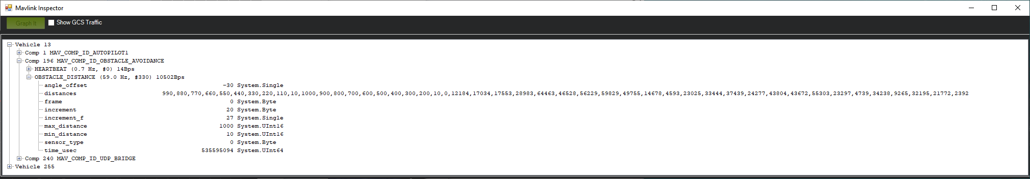
I am testing this stuff with an array of fixed distances:
SERIALx_OPTIONS for your lidar you need to unselect “Don’t forward mavlink to/from” then you will see it as a separate mavlink component in mission planner, select it from the drop down under the connect button then open the proximity display again and it will be the yellow high res display. The issue with it is that this is coming directly from the LIDAR so its a massive amount of data and will usually overload the telemetry. I used a 4g connection so bandwidth isnt an issue but it will make any telemetry radio choke as it starts dropping packets so use usb for testing rather than telemetry radios.
Yes! Thanks a lot! I would not have seen this trick in my whole life (although probably this is what should happen, since I was not looking at this other mavlink communication (other mavlink serial) in MP)!
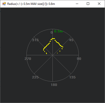
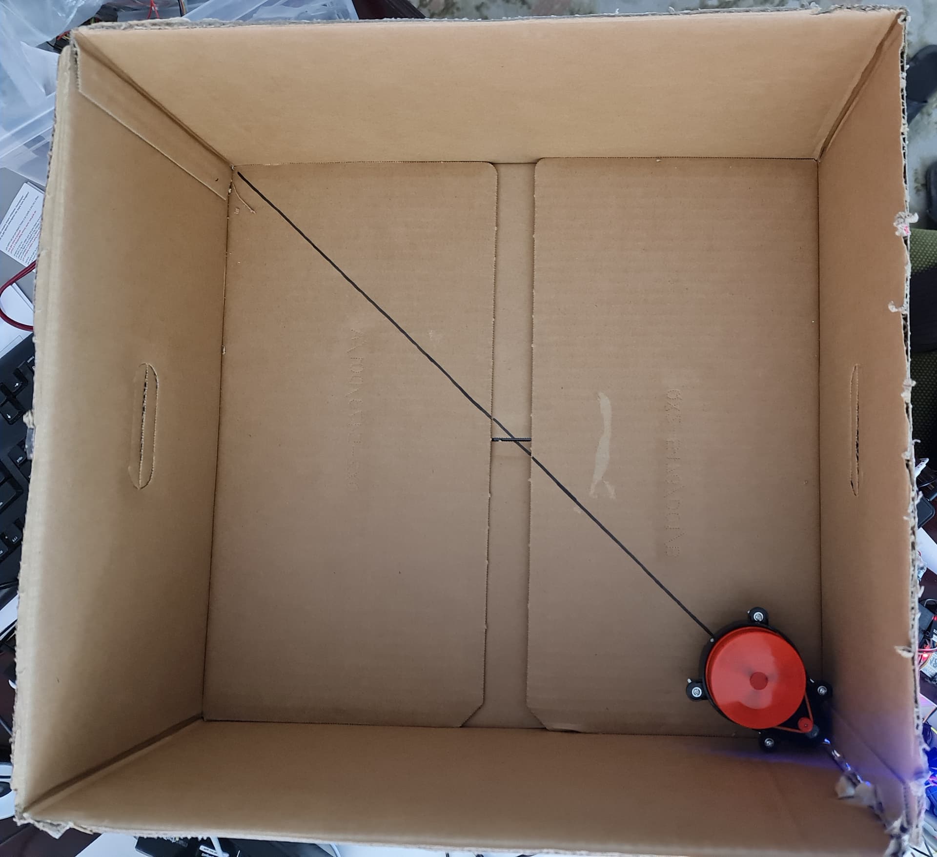
I received a XV lidar and tried it. I put it in a corner inside a box and with forwarding got:
But:
The library gives 4 measured distances per packet, and the code seems to consider only the first one (unless I miss something): Dist = (packet.distances[0] / 10);
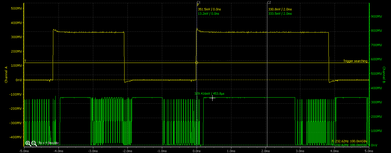
Apparently, after getting a library packet the code sends a mavlink message, instead of wating to get more. Introducing some time tracing:
(distance mavlink messages every 2 or 4ms)
Considering only integer numbers, you could send 18|15|9|3|2|1 packets/message (here 1). 18 would occupy the 72 distances maximum capability in one mavlink message, every 48ms at 250rpm, unless I miss something.
I havent really looked into that, the code was originally for a much slower system so thats why it updates one distance per packet as it would have taken a long time to do a whole scan but with this spinning as fast as it does then sending a whole 72 distances per packet would be far more efficient. but 18 packets is a lot less detail than mapping 90 into 72.
I will try and see if I can send 72 packets after each rotation
(I chose 9*4=36 for fit in the MAVLink inspector).
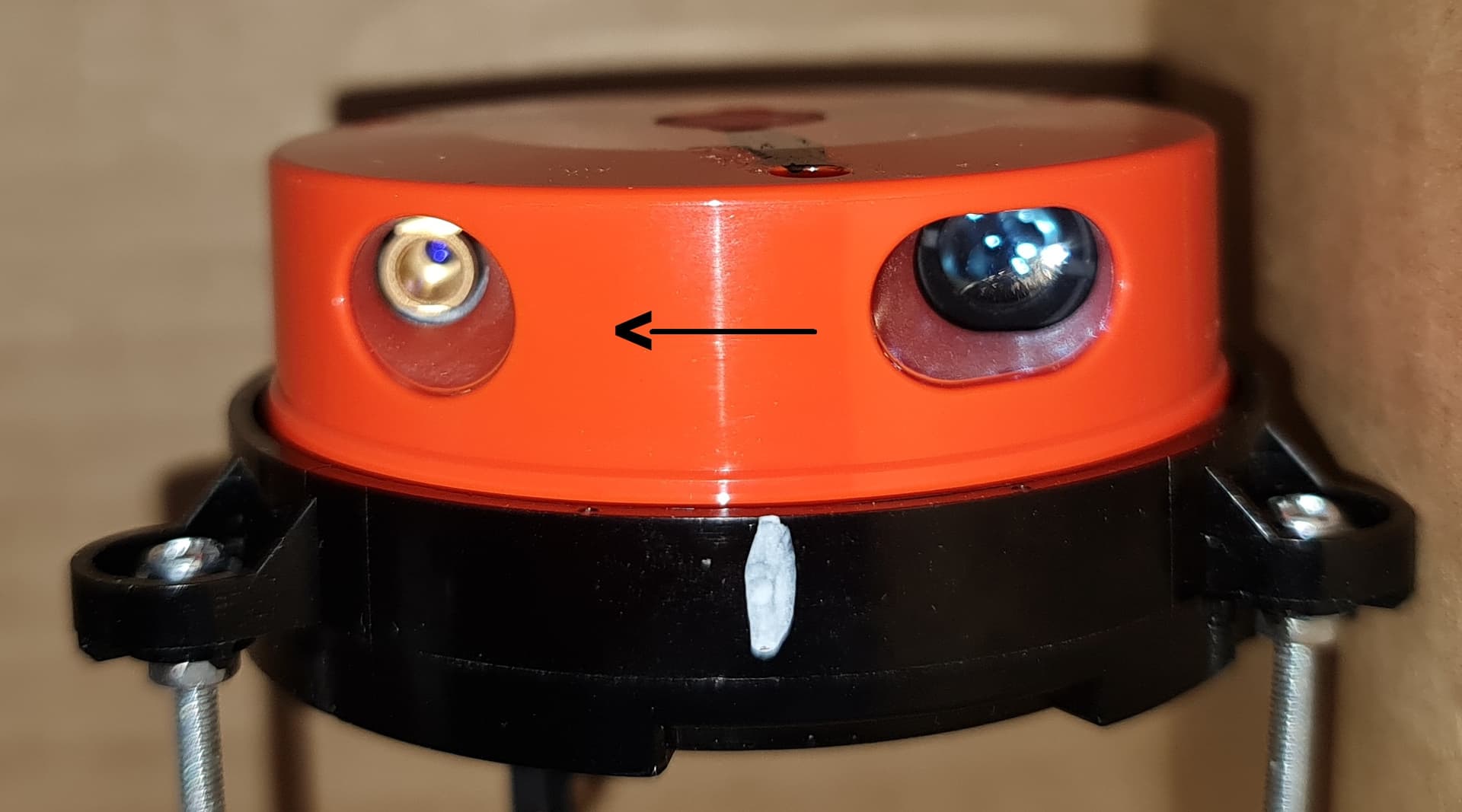
Here and there it is said that this lidar has a 10º deviation, apparently confirmed by above capture, but this is not clear: when the lidar (which rotates CW seen from above it) is at the center, the laser could be pointing at a box wall
I think the issue you are seeing in the video with the corner being offset is just due to the type of sensor it is, you only see differences like that at very short range., onces its further the difference is so small its negligible. can you show me your code for inserting all the distances into the one packet?
I have made a version of the code that waits for 90 lidar packets to arrive to get a whole rotation before sending a mavlink packet, it should reduce the bandwidth requirements enormously. I haven’t got hardware to test at the moment, It’s packed up while I work on my boats.
Is it possible to use the Laser/sensor and back PCB only for airplane landings and avoid the spinning thing as a whole + get rid of pdb altogether with the motor?
if its not spinning then its probably just the motor, there is no controller for the motor on the lidar its just a direct connection to the motor and they can be bought from aliexpress its a very common motor.
im back after a while, and im trying to get my rover back running with the LiDAR unit on top. The problem is, there were a lot of ArduRover updates since then. So I created a new custom firmware for the “Latest” version of the ArduRover with the Custom Firmware Builder, with the same settings enabled and disabled as my old version. After uploading it into my FC, it seems that the flight controller is not receiving any data from the lidar. All of my settings are set correctly, same as they were set a few months ago, back when everything was working. Everything is connected correctly to the board too. Am I doing something wrong? Or is it the lidar unit code that is outdated? I would rather be up to date with the ardurover updates. Thanks!
Yes, exactly. Then im going to analyze my connections again. Is there any way for you to tell me, which options and functions should be enabled/disabled in the Custom Firmware Builder? Maybe i frogot to enable some options…