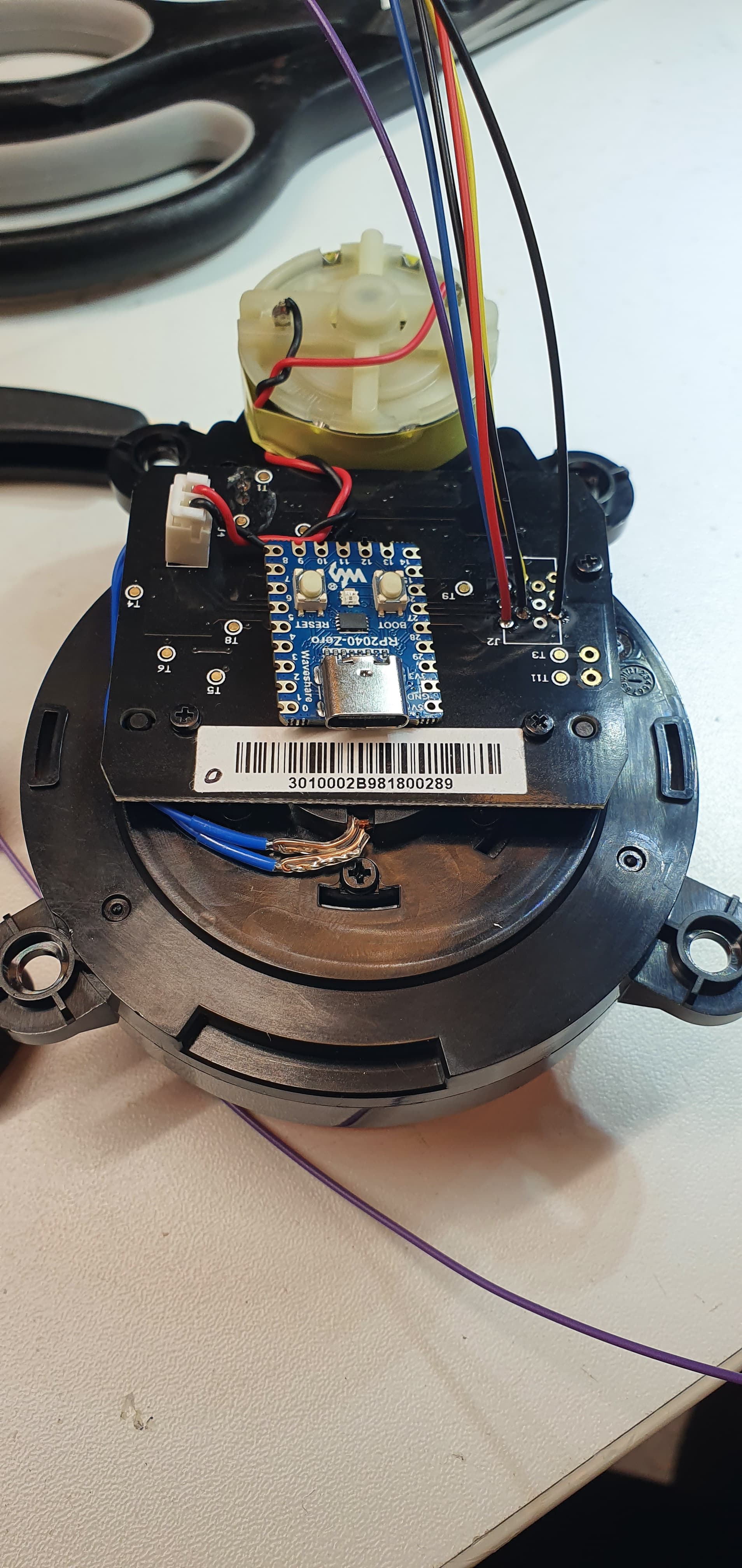
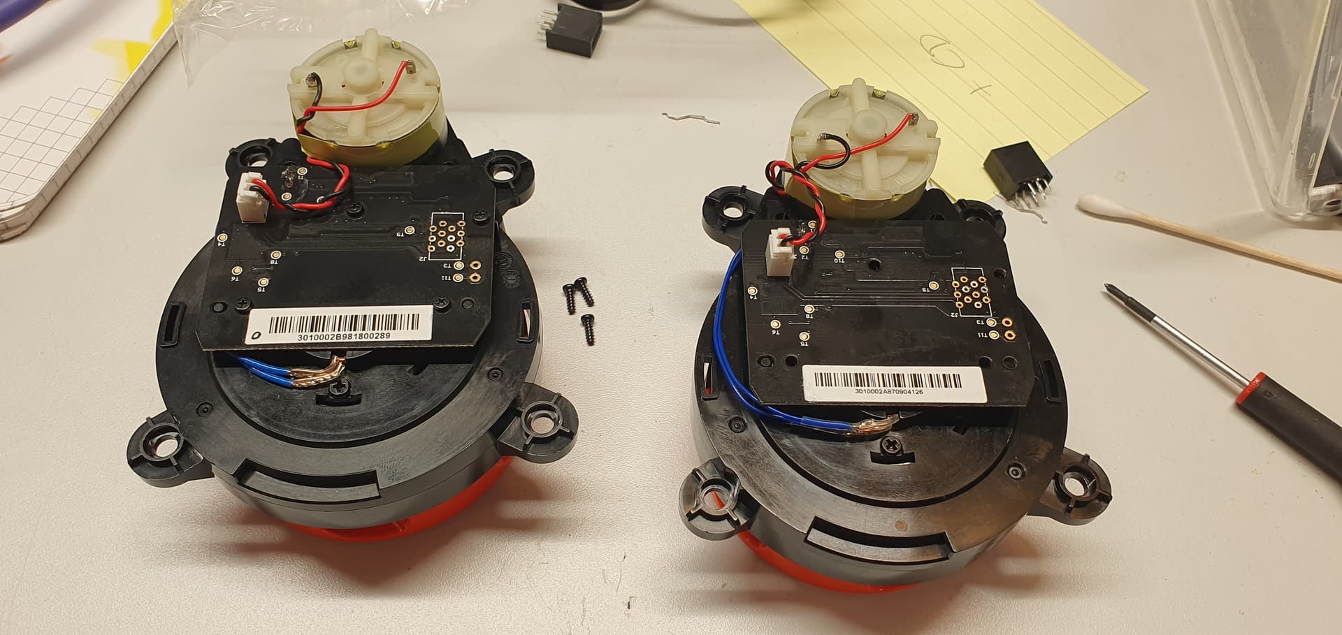
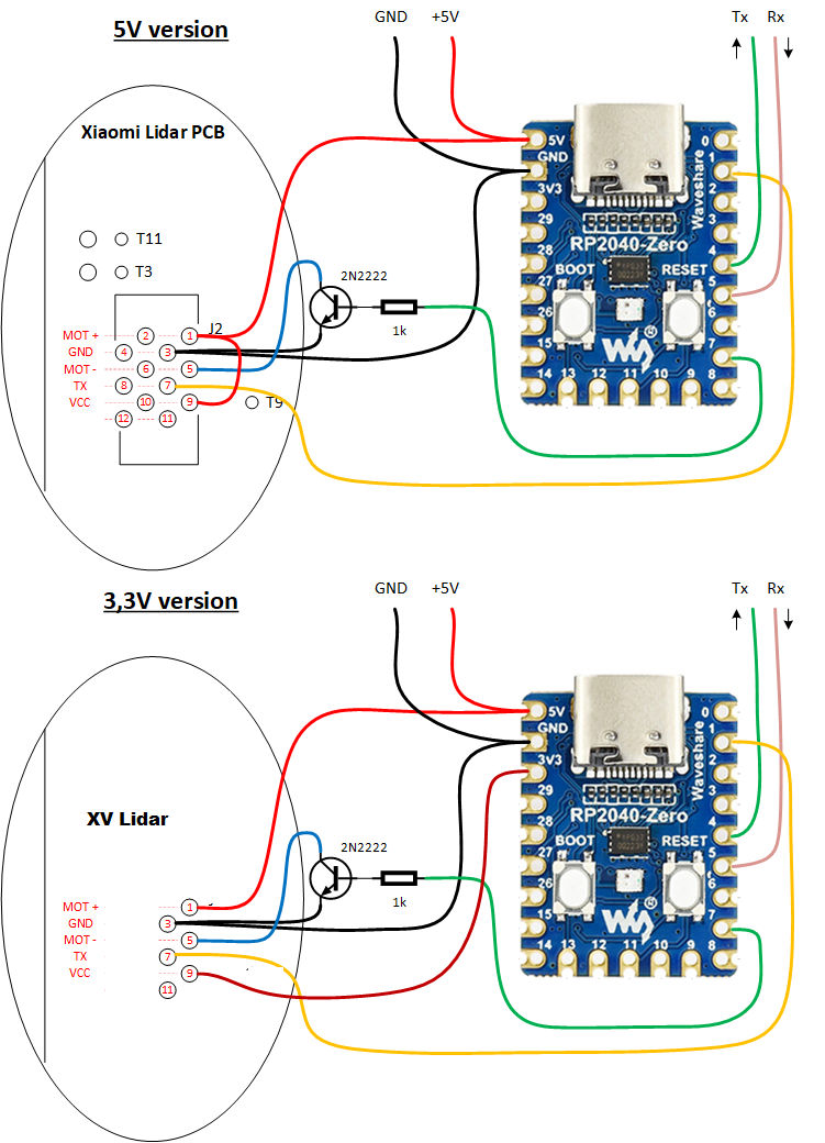
yep that listing shows its compatible with all of them so I think all of the Xiaomi lidars are 5v, i cant find where I seen that they were 3.3v. Im not sure where i seen that, I have been trying to find it.
I think the stickers are probably serial numbers, and not related to what machine they came from.
Ok… have tested the new code now… it starts Green for 2s then gets RED… i.e. the oposit of the expected behaviour… ;o). So i guess that i do have a communication problem… are you running your xiaomi’s on 5v ?
yes i run mine on 5v, It shouldn’t go green immediately It should start up red as thats set during the setup part of the program, green is only called if a packet is received. does the motor try and spin when it changes colour? as the pid loop is started at the same part of the program as the green led.
that looks promising, the PID loop is starting so its getting some data but its shutting down because its not getting enough power, it probably had a capacitor that keeps it running for a second or 2.
not sure why the LEDS are the opposite way around, I changed the code a little so it should change the led blue instead assuming its just red and green mixed.
I also added a line that will flicker the led every time a mavlink heartbeat is sent. thats only sent every 200ms to indicate its healthy if it’s getting new data from the lidar.
That was with 3.3v (was to lazy to go out to the garage to do the solder work at 0300 last night )
But just did a quick test with 5v and it seams to continue to rotate… did a couple of starts with good result… next is to do some more serious testing… and figure out how to get it working with missionplanner… can it be run directly to missionplanner via the usb/serial or do i jave to hook up a ardupilot platform in between?
if you open mavlink inspector and then select the usb serial the radar is connected to, then press CTRL+T it should try and connect in read only mode and you should see some mavlink packets coming from the RP-2040 Serial2 port., it wont connect as it wont detect a flight controller but you should see data in mavlink inspector when it opens the port.
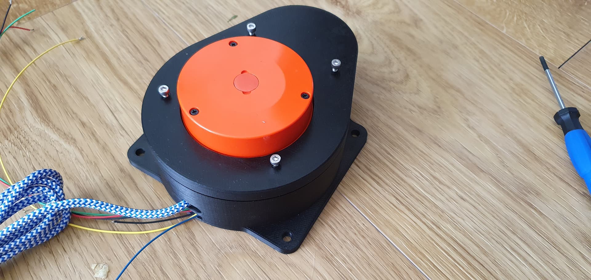
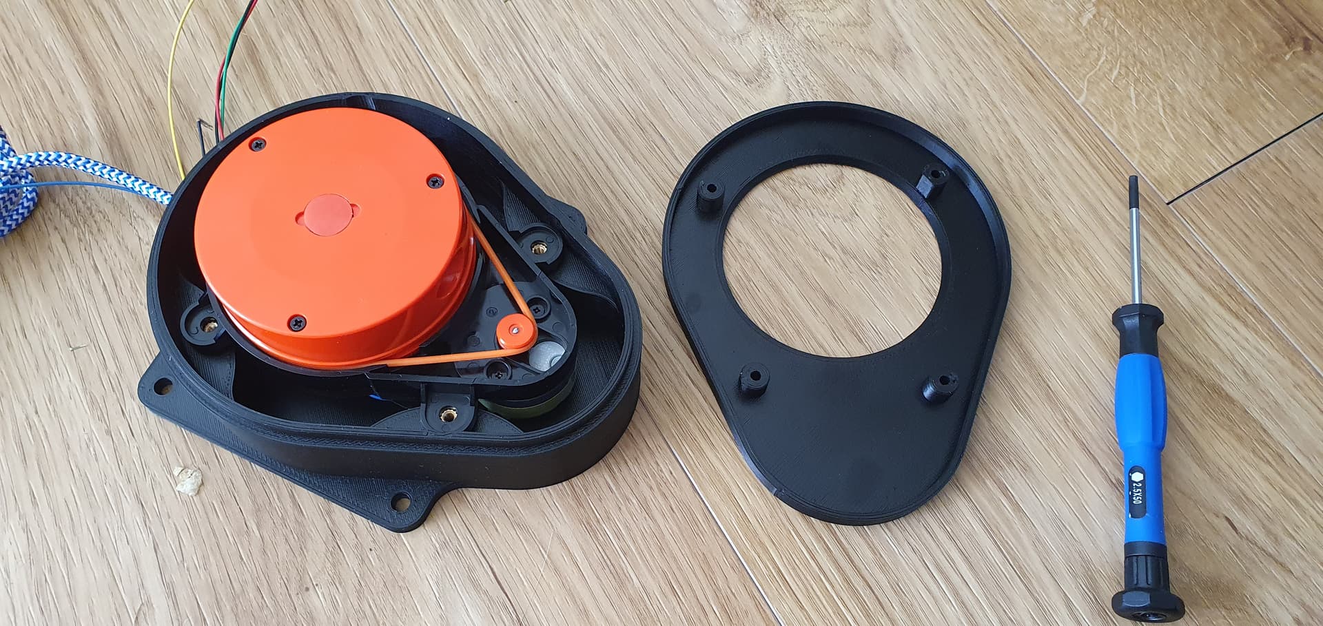
what is that 3d printed case you have it in? did you make that? the case i done is just a RP-A1 case that i resized, it doesnt look as good as yours lol
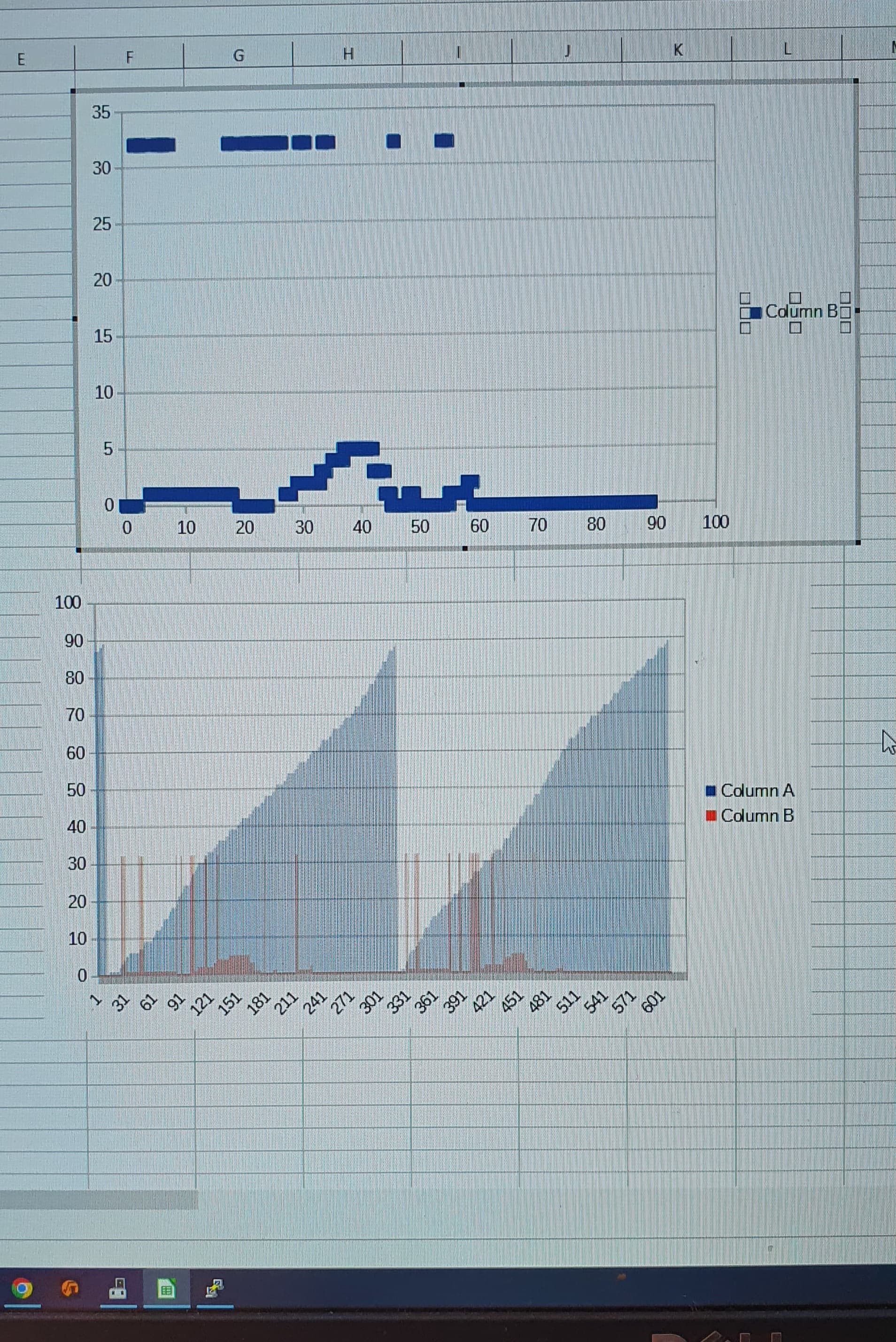
As i did not have anythinh attached to the serial2 port, I decided to just enable some of the debug prints… and catched those with a terminal-app (arduino serial montor did not allow me to copy long sets of data…) and then used some of the data and graphed it in libre calc.
And yes… its all working now…
The case is something i made up when i thought that your case was not compatible with my units… i erroniously concluded that the monting stud were not located as mine. My locations is still not 100% so there is some resistance to close it… but i have 3d-scanned the xiaomi and has halfway remodeled it in fusion360, primarely to get correct locations of the mounting tabs…
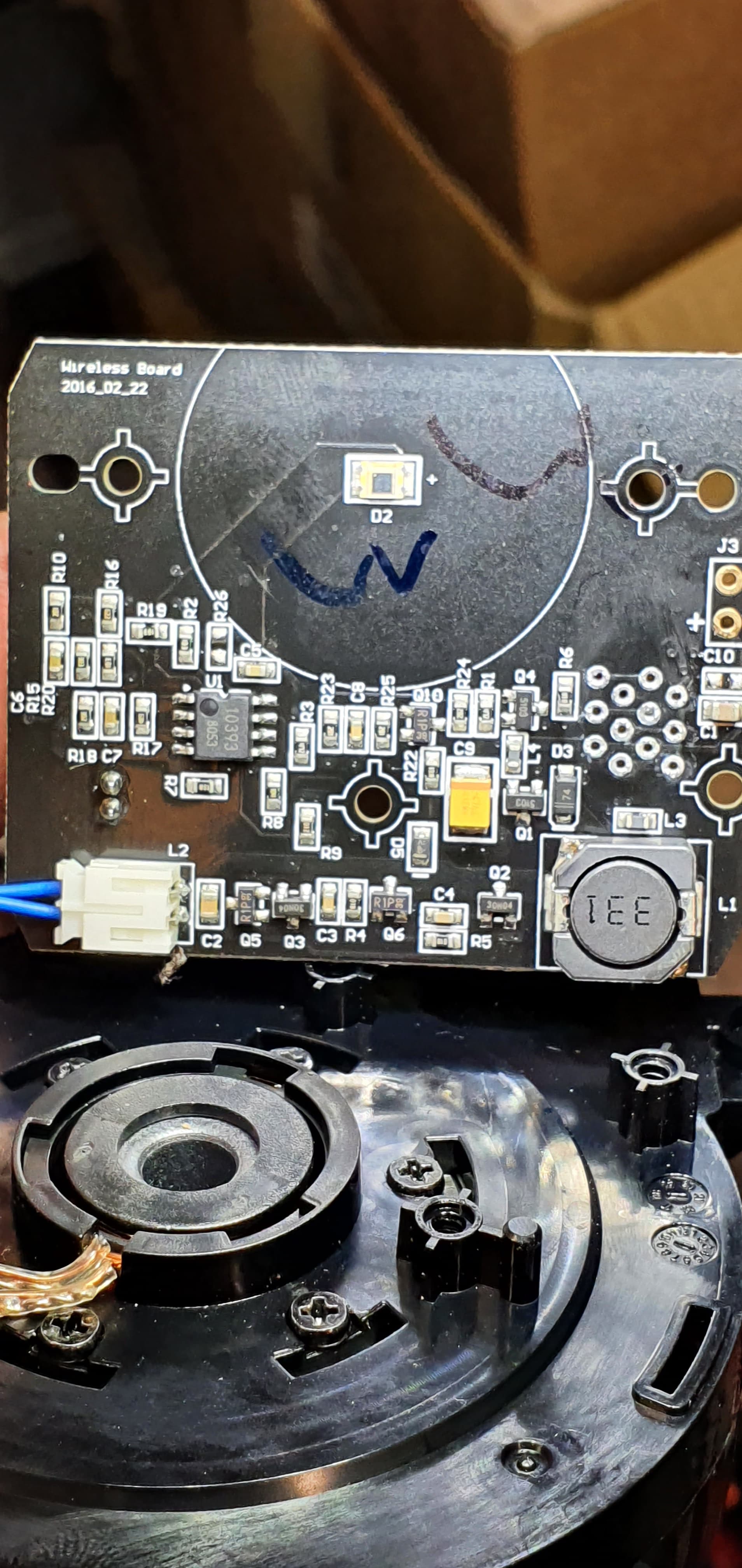
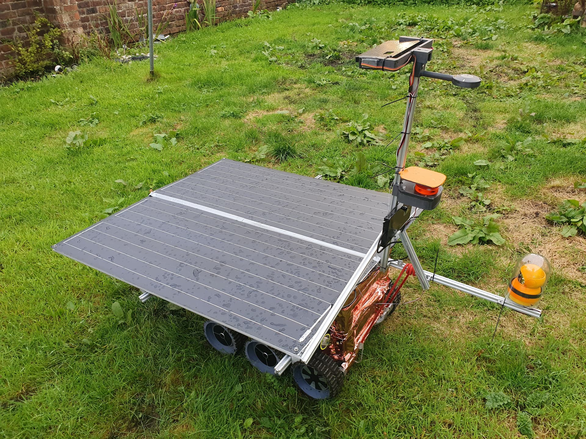
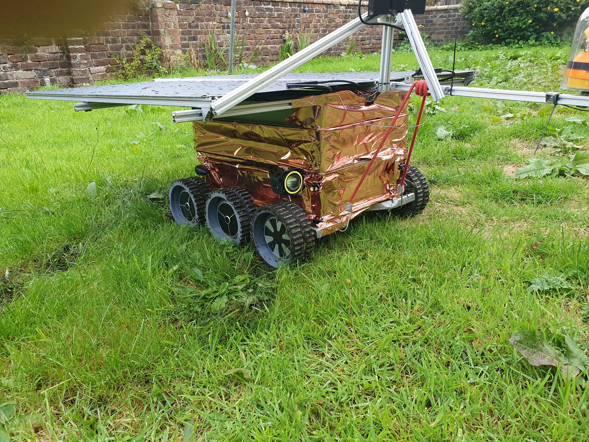
I left my rover outside last night in high wind and heavy rain, i added a small rain cover made from the base of a failed print to keep the worst off it but surprisingly when i got up this morning the lidar was still working! It was soaked to the point there was actually a solid film of water being held in place around the hole where the lidae was spinning.
I fully expected to destroy this lidar so I brought it in for examination and after pouring water on the lidar found that there are 2 drainage slots on the sides of the lidar, so any water just fets diverted out them away from any electronics.
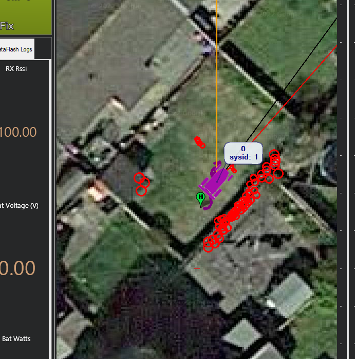
I have ran into a slight issue with testing, The flight controller keeps trying to forward all the lidar data to the ground station via the telemetry link causing it to overload. my understanding was that setting the system ID on the mavlink packet = 1 should cause the data to only go to the flight controller since its system ID 1.
ok after reading the mavlink routing page at Routing · MAVLink Developer Guide from what i can tell any message that doesn’t have a target system field will get forwarded to all other nodes. but from reading mavlink_msg_obstacle_distance.h there doesnt appear to be a way of adding target_system to the message. so is there any other way of blocking the proximity data from getting rerouted to the ground station?
Yes, tough I would suggest reducing the resolution of the data sent to the ardupilot. 5° resolution should be enough. Another option is to increase telemetry throughout as default 57600 baud is at 80% throughput on default MP settings.
I use usb over 4G usually so that link can actually handle the data but its my backup UHF link that really suffers, its just not designed for that datarate and almost nothing gets through. I knew there was a setting to limit it, but i just couldn’t find what it was called, the setting didn’t show when I searched the parameters for mavlink.
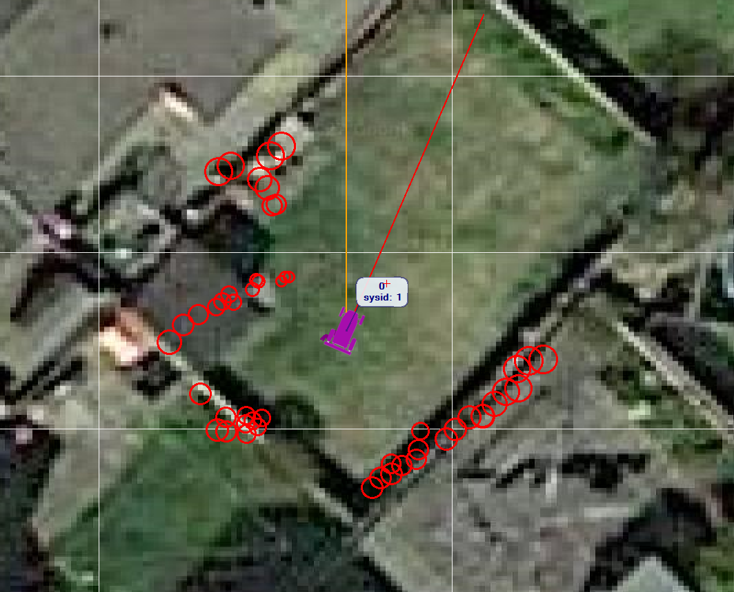
@VRquaeler that was what i was looking for, i set that and its stopped the torrent of packets from the lidar coming down the telemetry…hmm some more testing shows that i cant get the high resolution display if i set that, I didn’t realize that was generated from the data that comes directly from the proximity sensor.