An internal combustion, gasoline-burning engine was selected as the powerplant of the UnATRaP. As mentioned before, this was done for endurance, cost and ease-of-use reasons, but also because we wanted to experiment with IC engines a bit. As a result, instead of having to select battery capacity and number of cells, we had to worry about fuel tank volume, its placement and the routing of fuel lines.
The stock tank
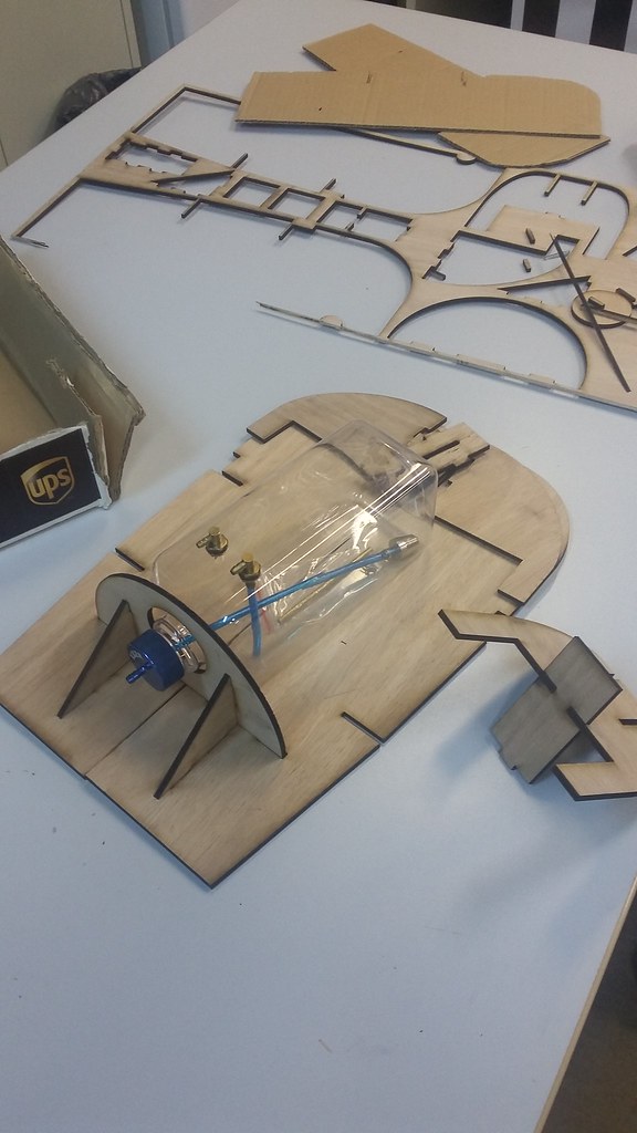
The initial fuel tank had 500ml capacity, was made out of hard plastic and had a suspicious seal at the tap. Its original installation position was occupying the section between the fake avionics panel and the battery hatch. The original design has a dedicated circular inlet for securing the bottle neck.
However, this tank was deemed too small for our needs. We wanted to go for something bigger, at the range of 1lt. This decision was based on experience rather than facts, but later measurements showed that the original tank wouldn’t last us more than 20mins of flight, which would be severely limiting.
More fuel
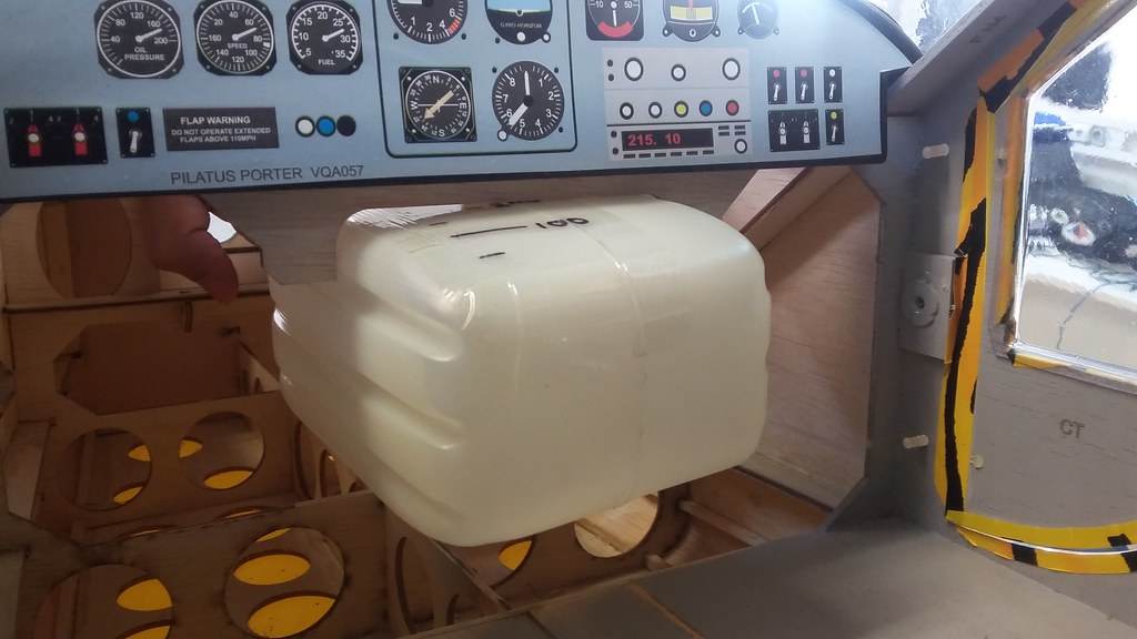
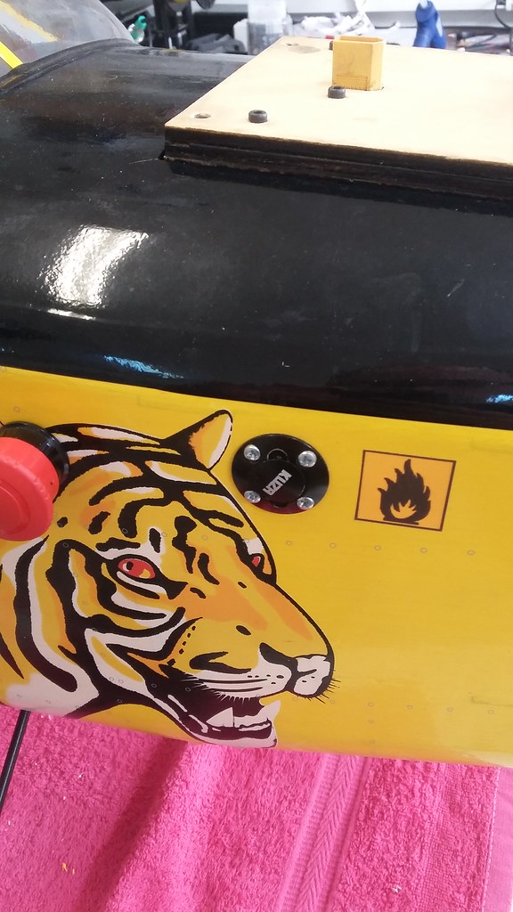
We upgraded and went for a 1lt KUZA tank, which has larger capacity and more manageable form factor.
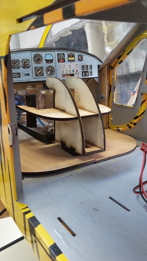
Initially, we wanted to have an installation which would allow for easy removal of the tank, for inspection and modifications. A wooden supporting frame was designed to envelop the tank and hold it firmly in place. Screws would allow the back section to slide forward, secure the tank and tighten down. The tank was also lined with tick foam, to prevent air bubbles from forming due to vibration, as much as possible. Wooden flooring was laid down over the fuselage ribs to support the tank and its frame.
More space
Unfortunately, this solution was protruding behind the avionics panel and was taking up too much valuable space. Reluctantly, we ripped appart the tank frame but kept the flooring. Our reluctance was mainly due to the fact that the whole assembly was put together with two-part epoxy glue.
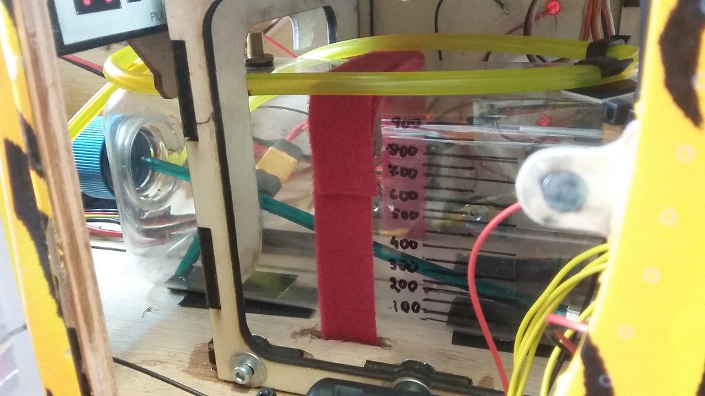
In the end, we used Velcro to position the fuel tank bare, onto the flooring and battery ties to hold it firmly in place. This thing isn’t going anywhere soon.
Between the lines
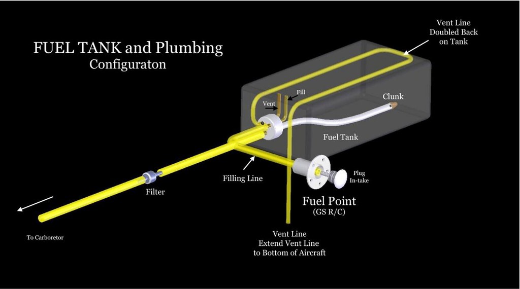
Three fuel lines are connected to the tank. The first one is the fuel feed to the carburator. While relatively straightforward to route, there is one nuance that one should keep in mind. If the fuel level is lower than the carburator, then the latter should fight against gravity, when generating low pressure to pull the fuel towards the engine block. This usually isn’t a concern, as the pressure difference is enough to overcome gravity easily. In our case, the tank is slightly lower than the fuel intake of the engine and we don’t have a supply problem.
BUT, the one time we did have a problem with the (probably dry) carburetor which wouldn’t pull fuel no matter what. If the fuel level was higher than the carburetor, chances are that gravity would help.
The refuelling line was also easy to route. We bought a fuel tap, drilled it to the side of the fuselage and added proper annotation.
Finally, the DLA engine manual had a note on the installation of the overflow line. A loop of tube was shown to go backwards and over the fuel tank, before going towards the front once more. We thought that this configuration had its use in 3D airplanes, to avoid fuel from draining out in out-of-plane manoeuvres, thanks to the communicating vessels principle. Still, we dismissed this case as unrealistic for our situation and went a little stingy and place a smaller loop, 1/3 over the tank.
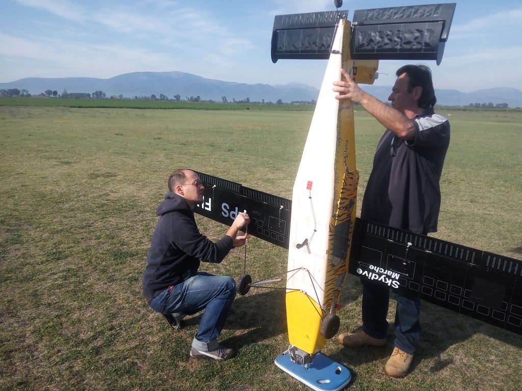
While this was partially true, we had missed one more case, which we immediately realized on the first field day. We calmly raised the plane onto its nose to perform underbelly integrity checks only to see the fuel tank drain from the overflow line onto our feet! We didn’t make the same mistake the next field day…
This concludes this part of the UnATRaP blog series. If you have comments or recommendations, please let me know. Until next time!
Previous article: Part 3: Tailwheel and Rudder
Next article: Part 5: Hardpoints and Mounts