The 8-LED PCB strip that I am using is labelled as WS2812B, so I assume that the LED chips (surface mounted) are actually WS2812B.
Yes, that is correct.
Hunting around on the interweb reveals that the WS2812B colour sequence can be either RGB or GRB and it appears that the through-hole WS2812B use a different colour sequence (RGB) to the surface mount WS2812Bs which are GRB …
I am not sure if you are agreeing with me, or contradicting me?
I probably should not have finished my comment with a question-mark.
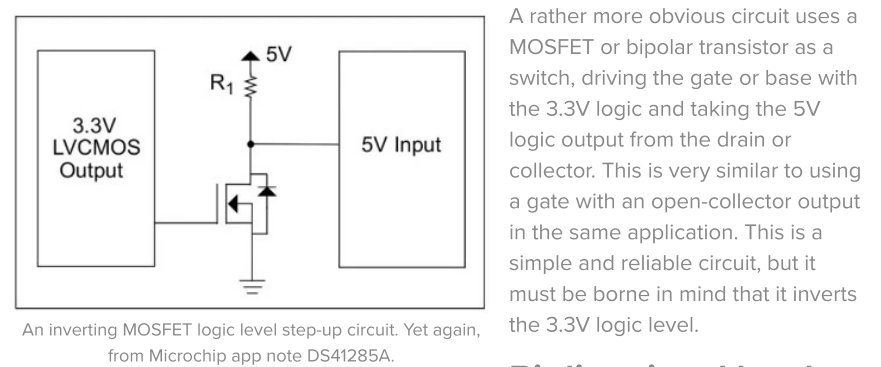
But, this is how I understand Tip #6 (on page 8-6) works.
It talks about an N-channel FET and the associated schematic diagram shows an N-channel FET.
When the gate of the N-channel FET is pulled high by the 3.3 v output, the FET turns ON and the drain goes low, which is the 5v input. Hence the signal is inverted. Which means that it is not suitable for our application.
From the literature there: When switching the input from a ‘0’ to a ‘1’, you will have to account for the time the input takes to rise because of the RC time constant formed by R1, and the input capacitance of the 5V input plus any stray capacitance on the board.
That seems Hin -> Hout, with delay.
The symbol seems a depletion n-channel transistor. Microchip should make clear which one behaves as in the descriptions.
From the symbol it seemed a depletion mode n-channel fet, but, although they admit positive and negative Vgs, their working is documented for negative ones (0V off, negative voltages on).
That paper is ten years old. Several things can happen:
-The transistor there is a mysterious or ideal component.
-Errata: should say: When switching the input from a ‘1’ to a ‘0’…
-Let the author of DS01146B, chapter 8, tip #6 explain it, or someone working in Microchip. It is a very big company which recently acquired Atmel.
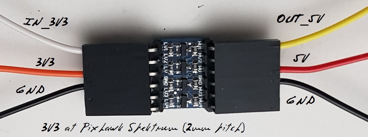
So let us stay with the simple level translators widely available, cheap and requiring minimal soldering (and no cutting). With dual ones you can feed two strips, with quadruple ones four; imagine cutting and soldering for four strips.
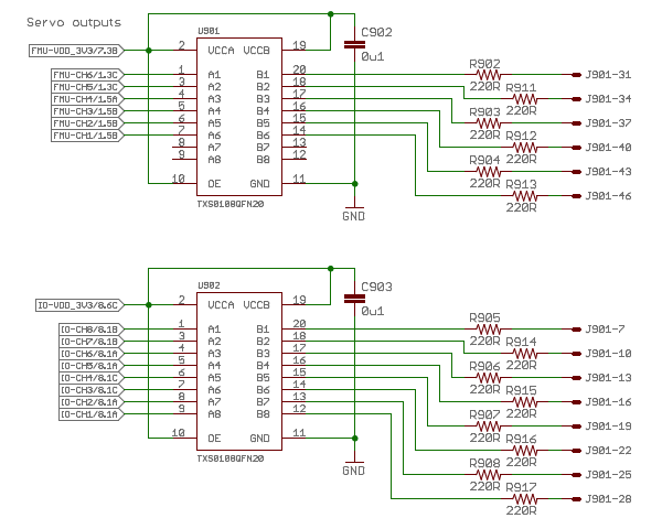
Wait a minute. On the Pixhawk, both AUX and Main signals come from TXB0108:
( 8-Bit Bidirectional Voltage-Level Translator with Auto-Direction Sensing and
±15-kV ESD Protection)
with separate VCCA (recommended 1.2V to 3.6V) and VCCB (recommended 1.65V to 5.5V), but both are connected to 3V3.
Vohb has minimum VCCB-0.4V, roughly 2.9V (low).
So it seems that if VCCB were connected to J901-VCC (moreless servos/ESC’s external supply) no level translator would be necessary, but this implies a redesign of the PCB.
Output signals would be truly 5V (or external supply). Any drawback?
I am trying to set up a WS2812 led to display the standard NTF notifications, but I get no output on a CubeBlack. I have set the following parameters:
NTF_LED_TYPES to 255
SERVO10_FUNCTION to 120
BRD_PWM_COUNT is 4
NTF_LED_OVERRIDE is 0
what other stuff haw you got setup on the servo outputs?, it could be a grouping issue. You also have to power the LED’s, ie plugging only some NeoPixel’s in wont work you need a bec also.
Nothing else is connected. For good measure I moved it to Servo14 to avoid potential grouping issues. I set NTF_LED_TYPES to 455 and now it kinda works, but displays a strange behavior:
The signal is level shifted, but insted I also tried reducing the supply voltage to the LEDs to 3.3V. Same issue.
Only one LED is expected, if you want more you can flash latest and use the new parameter (warning this not stable firmware might be other bugs ect). Irregular could be something to do with the level shifting, it looks like its missing some commands. You could try directly from the servo output.
Only one LED is controlled, got it. Regarding the irregularity: it makes no differene if I connect it directly, level shift the signal, or supply the LED with 3.3V. The irregular flashing/missed commands is always the same. Chnaging to a different Servo output also makes no difference.
I just tested it on a Pixhawk 4 and the LED blinks as expected.
No luck with the CubeBlack.
edit. Further investigation:
I just tried resetting the parameters to default and only changing the parameters NTF_LED_TYPES, SERVO14_FUNCTION and BRD_PWM_COUNT and like this it works as expected. After reapplying my parameters, the irregularity/missed commands is back. Maybe someone could take a look at them: NeopixelIssue.param (18.1 KB)