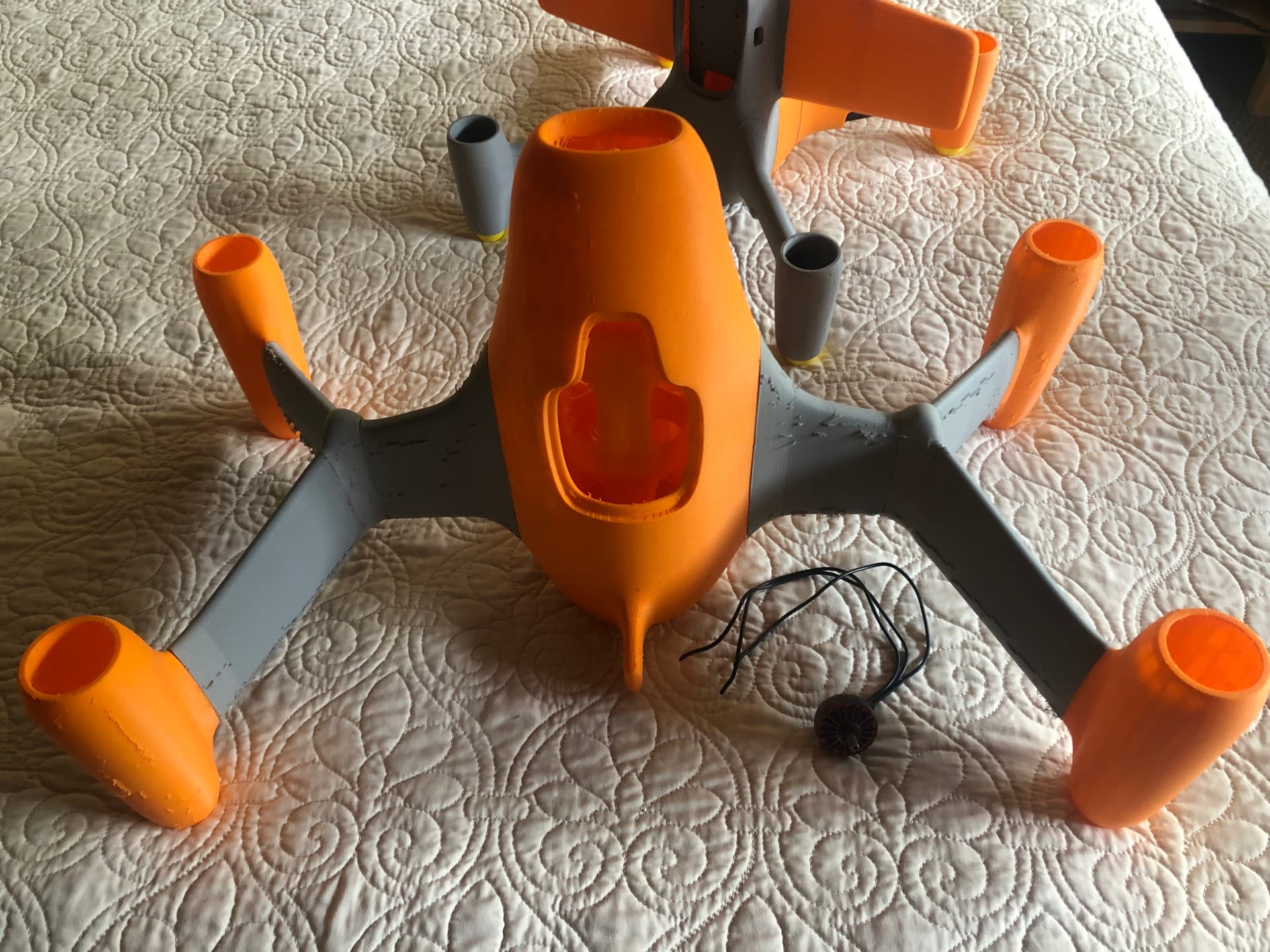
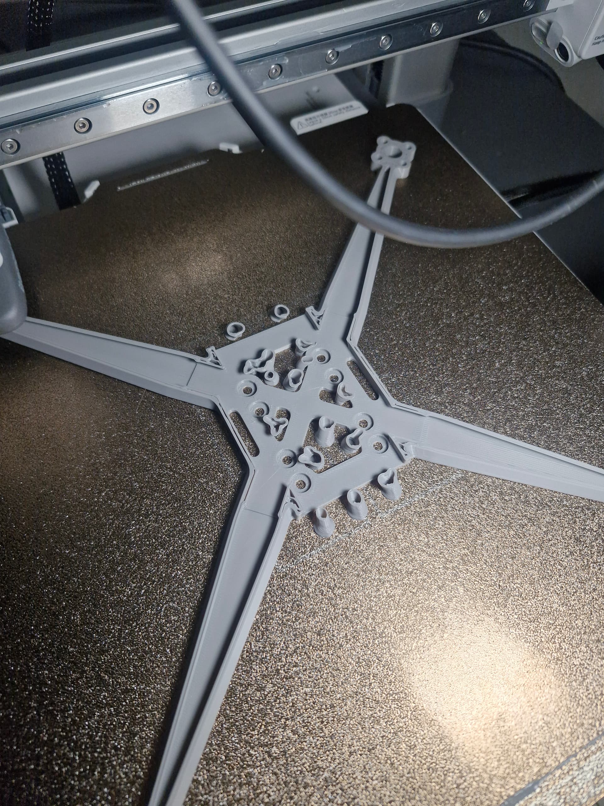
The holes in the arms are closed, baffles inside the arms. 3 in each. Support beams from arm to arm, thin to reduce weight but keeping the vertical thickness greater to reduce flex up and down along with the torsion of the arms.
I have some combinations with the baffles, support beams and solid arms I would like to try just to figure out what helps the most. Adding one at a time to see the effects.
I use an Ender 3 v3 and a bambulab A1. I have no stringing so far. Had some issues with the extruder slipping on the V3 but got a new high flow nozzle and switched to creality hyper pla which solved the issue. I’ve experimented some with retraction distance. I reduced it wince I noticed the V3 didn’t get the filament out as quickly as it needed on small detail resulting in the beginning of the line missing. It has 0.8mm as default, I tried 0.5 but got stringing. Now I’m at 0.7 I think. And I increased the priming speed from 40 to 50 as well.
Do you have your extruder mounted on the head or at the side with a ptfe tube?
Side. I did try a aftermarket swiss feeder but having all the machines the same was less confusing for me. I might try the 0.7 My A1 is nice for small parts.
I used and ender 3 v2 neo with the extruder mounted on the side and I used as high as 3-5mm in retraction on that one. On my A1 I use 0.8 with no stringing.
As for the theoretical design, I’ve added the tilted baffles, as well as most of the holes. Some on the side got removed to not interfere with the baffles.
I’ve printed 3 more version so far.
1 solid arms
2 solid arms and baffles
3 holes in arms and baffles
The baffles gave great results stiffening up the arm, especially the torsion resistance. Although making the arm solid with no holes made the greatest difference torsion wise.
I tested the one with holes and baffles and the one with baffles and solid arm against my original frame, no baffles and holes in arms.
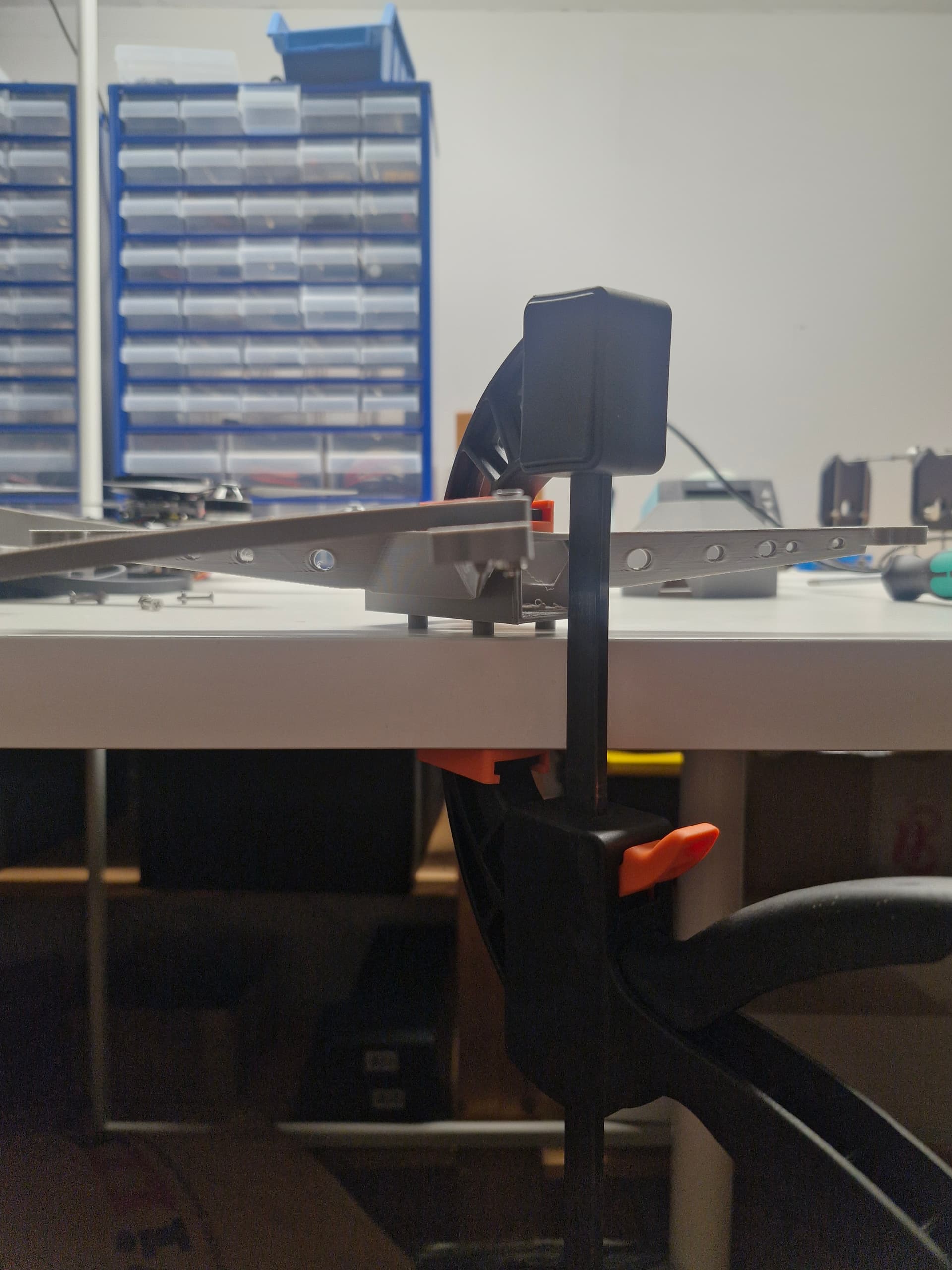
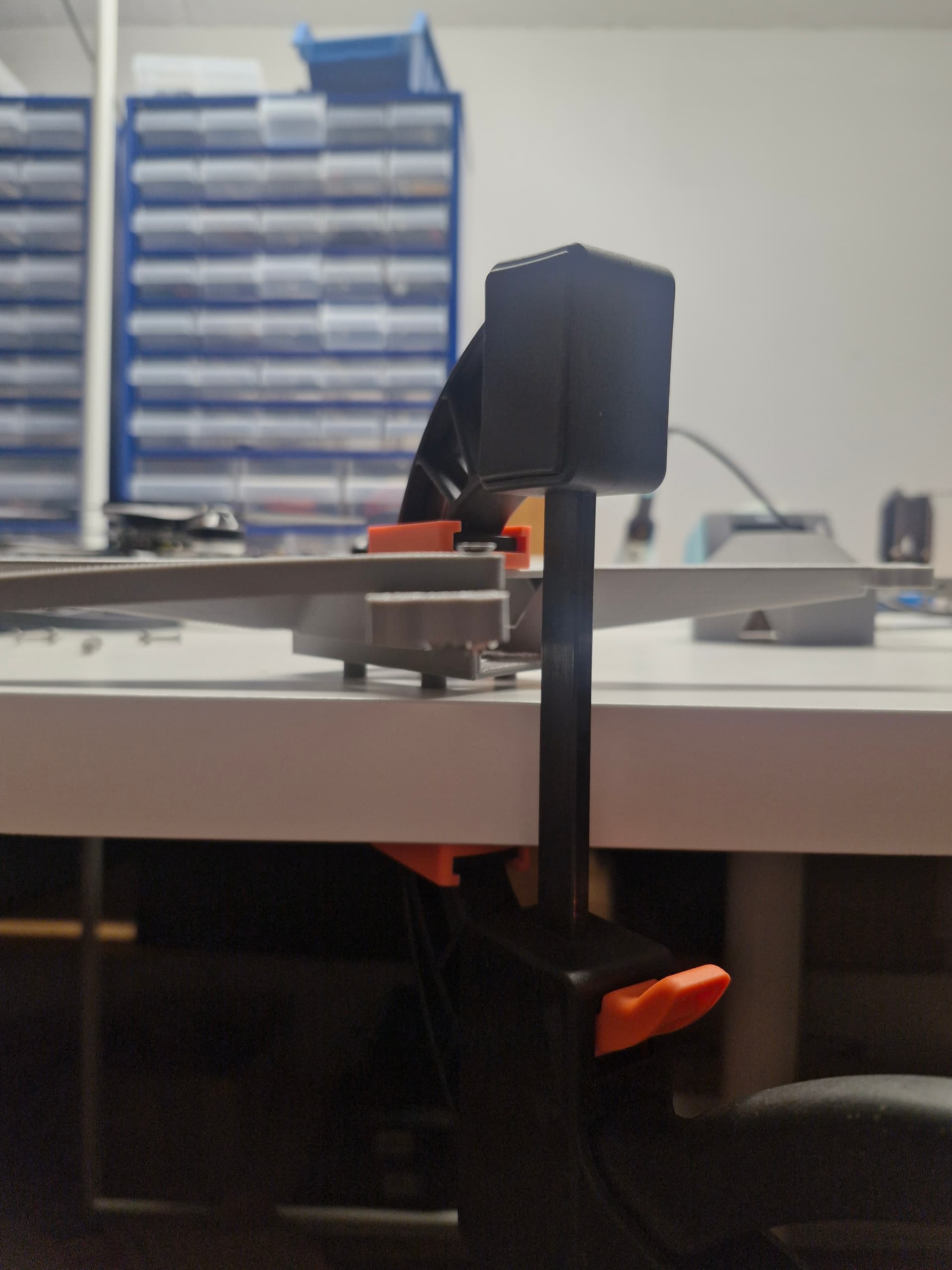
My test consists of attaching a small 3d printed stick to the motor mount ang hanging weight on it. Than comparing the rotation/torsion of the arm.
My stick is 155mm long and my weight is 164g. That should give me a torque of around 0.25 Nm. I measured from the center of the motor mount to the center of my weight to get it all right.
First pic. This is the frame with holes in the arms and no baffles. The torsion is quite substantial and I can see why is would cause instability in yaw.
Second pic is with baffles but holes in arms. Not at all as many holes since the baffles took up some space along the wall of the arm. This dramatically improved the torsion resistance. But it can still bend at least a couple of degrees.
I didn’t test the solid arm only with no baffles. It seemed as stiff as the one with baffles and solid arm. There’s surely some difference but with my 3d printed stick bending under the weight as well I couldn’t get a good result testing them against each other.
I haven’t gotten the time to flight test all of them yet. I’ll try to get them done by the end of the week depending on the weather. It’ll be interesting to see how the vibrations are affected by the stiffer arms and if my small yaw events can be minimized.
And with the frame being this stiff I don’t think I’ll be needing the support beams shown in my CAD design anymore. Those will probably just add more weight than support. But it would still be interesting to see the difference in the log with or without them.
The materials comment I made applied to my typical work projects which are unrelated to this hobby. But there are some parallels with structural design. That said aluminum is generally not a good material for a multi rotor frame.
If you could find other uses for it a desktop cnc router is not too expensive. I’ve found some around 600 usd that could cut aluminum. It would take lots of time for such a machine but surely it could be done. I was thinking about getting one for another project my brother has regarding simulator steering wheels, but since we didn’t find any other use for it after that 600usd became quite expensive.