Technique to expand Roll and Pitch Rate PID gains without instabilities

I am writing this discussion topic illustrate how I used the filter to successfully reduce the instability to increase the P and D gains. I’ve read in the Copter traditional helicopter tuning section about tuning the PID gains and that in most cases helicopters are limited in the P gain for pitch and roll due to aeroelastic instabilities of the airframe. I’d be interested in learning about any work that has already been accomplished in this area.
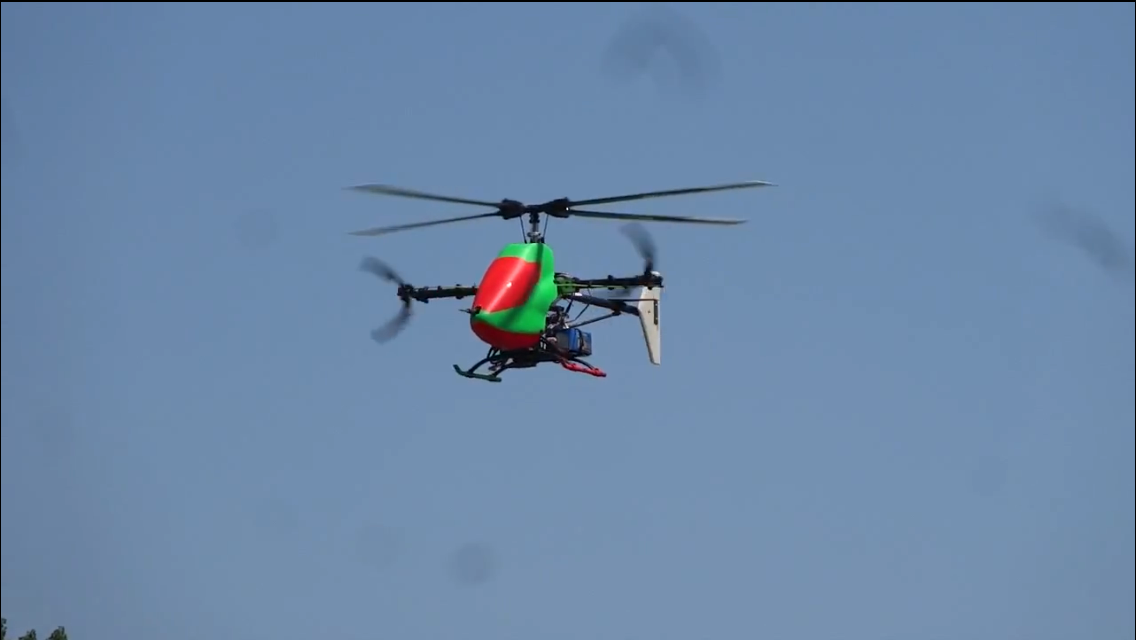
I am relatively new to the ardupilot community. I have been working on a special project with an electric helicopter modified to fly fast. Basically I took off the tail rotor and added two forward facing variable pitch propellers (tailrotors). I have made several modifications to the AC 3.3.3 software to include adding a new compound heli frame, adding the airspeed sensor from arduplane, and a turn coordination logic. In expanding forward flight speeds, I found that there was a significant pitch oscillation of about +/- 8 deg at around ½ hz frequency. Before expanding the airspeed envelope, I wanted to adjust the flying qualities to remove this oscillation.

In tuning my helicopter, I found my instability to occur at approximately 6.2 hz. So my thought was to use the PID low pass filter to filter out the instability and enable the P-gain and/or the D gain to be increased. So the big concern with using a low pass filter is with degrading the response of the Heli to control inputs. To determine the effect of the filter I performed frequency sweeps while hovering. I used matlab to do a spectral analysis to look at the gain and phase of the input and output. The first thing I did was reduce the filter cutoff frequency. Once I was happy with the filter frequency (I ended up using 4 hz), I increased the P gain and did another frequency sweep. I was able to increase the gain by 80% of my initial value with no issue. If I would have used this gain with the filter set to 20 hz, the instability at 6 hz would have been horrible. Now comparing the frequency response of the higher p gain to the one with the 20 hz filter frequency, it can be seen in the graph below that there is slightly more phase bandwidth but overall there in no loss in aircraft response.


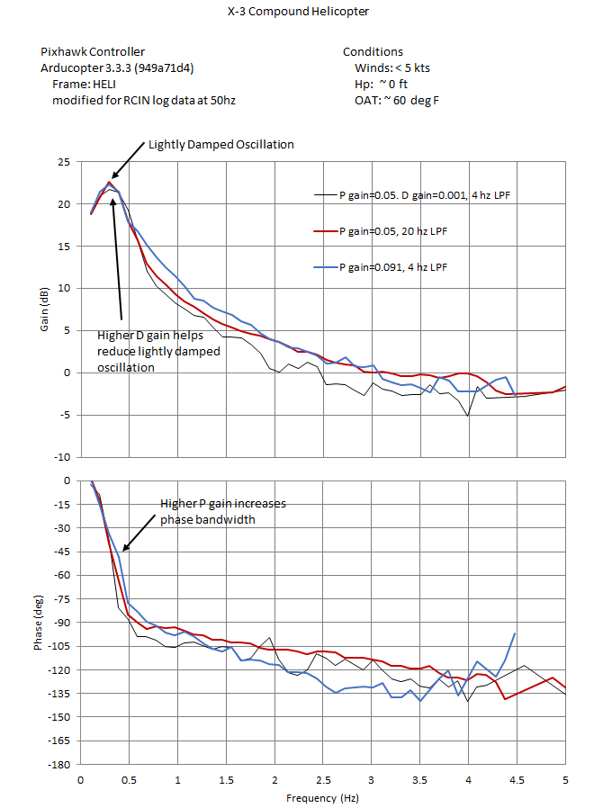
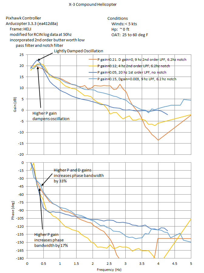
I did another frequency sweep with my baseline with P=0.05, cutoff freqency of 4hz and then increased the D gain to 0.001. Again, if I had done this with the 20 hz cutoff frequency, the instability would be terrible. In the graph above, it can be seen that there is slightly more phase and gain loss however it does help damp the lightly damped oscillation. I think the P gain would also improve damping of the oscillation but I wasn’t able to get the P gain high enough without having the instability start showing up again. With it so close to my cutoff frequency, the low pass filter cannot attenuate it enough. In order to really target this instability, I am planning to implement a notch filter. I think this would be a great improvement and allow higher p gains for the Heli frames. Has anyone done something similar to this? I will post an update once I incorporate the notch filter and test it.

2 Likes

Awesome, exciting news!

I have been on the default filter frequency is set to 20Hz feel wrong, because each helicopter body state are different, very different mechanical, and then with a different main rotor speed, the body’s vibration frequency certainly has many combinations . Therefore, because the filter frequency is not better with ESC GOV mode, the main body vibration, which leads to slightly higher Rate P will cause shock, so the debugging had to reduce the rate P to very low degree.

At the same time, I understand that reducing the filtration frequency less than 20Hz below, will bring the decline in flight stability, the role of the rate P weakened. It would appear that the setting of the filter frequency and the setting of the rate P are indeed more difficult to balance.

Your role in this experiment is huge, and look forward to your further testing, and I wish you success to find the filter frequency and rate P directly with the best choice!

1 Like

Yes I agree that each aircraft will have instabilities at different frequencies that limit the rate P gain and the frequency of the instability is dependent on many things. However as long as the frequency of the instability is above 5-6 hz, this technique should enable higher P and D gain values. At some point though, the instability will appear again. That is why I’ve chosen to use a notch filter and the LPF to really knock down the magnitude of the instability.
For now, it’s worth using the LPF and set it to 4 hz. Then tune your heli again to see what additional P and D gain you can achieve before seeing the instability again. I’ve seen that setting it to 4 hz doesn’t effect your ability to control the aircraft.
I hope to have the change incorporated and test it sometime in early December.
Thanks for your reply!

I tested the performance of the AC3.4.2 firmware on the T-Rex500, including stability, AltHold, Loiter, Poshold, RTL and Land. The basic performance are quite good, the default parameters did not occur significantly jitter. However, in Loiter mode, the operation of the aileron, the aircraft did not posture reaction problem, I put the situation report published here, you can refer to:

http://discuss.ardupilot.org/t/ac3-4-2-firmware-version-loiter-mode-aileron-operation-problems/13004/5

Bill, fascinating work here. I have been wanting to build a vehicle like this but haven’t got around to it yet. Can you talk a bit about what sort of performance you are seeing out of it?

I’d love to see a PR for the compound heli. And I’d also love to see the airspeed sensor, as I really want/need to implement VNE logic, which can currently be exceeded in Auto mode when flying upwind. And the turn coordination, something I’d love to see as well.

I can’t comment much on your controller work. But I will say that I don’t think I’ve got the controller quite right. I have thought about backing it off from a cascaded AngleP->RatePIDFF. And maybe change it to a AnglePID+RateFF or something. Some other things to think about, separate filter rates for the Rate P and the Rate D.

Rob,
Thanks for your interest in my project! I’ve never created a pull request. I can do that but here is the link to my branch of AC3.3.3.

You will find the commits for each of these changes. I will be committing my recent changes to implement a notch filter to allow increase P and D gains.

To follow up on this. The compound Heli code does not support autonomous flight (i.e. There are no control laws that give the auto mode control of the props as symmetric thrust. Currently I am flying my model with a mechanical mixing for thrust and directional control. But I have tested my code in the sim.
The airspeed sensor works great. I even use it as input to the turn coordination.
The turn coodination feature is still being tested but mostly complete. Trying to fine tune it on the actual helo. It works pretty well in the sim. If you still think my changes are worthy, let me know and I’ll figure out the pull request submission

I made a pull request a while back that included support for a compound helicopter I built. I basically used desired forward pitch in most flight modes as a proxy for desired forward thrust. It works very well in practice, even in AUTO.

I decided to remove the compound part from the pull request when an unrelated AP_Param refactoring introduced an issue I couldn’t figure out, but the old compound code is still available here.

Fredrik,
I should have given you credit. My work on the compound Heli frame was mostly based on your pull request. It looks like you developed that on AC 3.3? I moved it into my branch of 3.3.3 manually because I didn’t know how push your changes in using github. I don’t have intentions on flying mine in auto mode but I’ll have to look at your implementation to tie thrust to the desired pitch.
Thanks again!
Bill

Progress Update:
I implemented a notch filter into the AC_PID code. Also I modified the first order low pass filter (LPF) and made it a 2nd order butterworth LPF. I had difficulty adding a new parameter to allow me to change the notch filter center frequency with out recompiling the code. I would really appreciate any help to add this new parameter.
After verifying in the SITL that the new filters were working, I conducted several flights to investigate the effect of the notch and low pass filters. The notch filter alone was able to suppress the instability. Using both the notch filter and the low pass filter, I did not see any instabilities up to the highest tested P-gain value of 0.12.
4hz_filt_freq_sweep spectral analysis.pdf (100.6 KB)
The graph shows that the light damped mode is becoming more damped as the P gain is raised now that the instability is no longer a concern. It also shows in the phase plot that phase bandwidth (frequency at phase of -45 deg) is not greatly affected by the notch filter.
During my build up tests I did notice that the instability showed up at the baseline P-gain value of 0.05 with no notch filter and the 2nd order LPF set to 20 hz. I had not seen the instability at this low of a P-gain with the original LPF. I suspect that the 2nd order LPF DC gain is higher and causing this issue. To keep continuity with the code, I may investigate just using the notch filter with the original 1st order low pass filter and removing the 2nd order LPF.
The next step is to see how far I can push out the P and D gains before I see the instability again. I will look at reducing the FF gain to zero. Hopefully this can allow somewhat carefree Heli tuning. The biggest draw back to this solution is each user will have to determine the instability frequency and then set the notch filter to that frequency. If the instability frequency is below 5 hz, I suspect the notch filter might affect pilot inputs.

Very concerned about your updates!

This in-depth optimization, will be able to traditional helicopter PID debugging and cooperation between the helicopter architecture to a new height, I am very looking forward to these codes can be improved, and the smooth integration of the firmware to a later version, refueling ,Support you!

I wish smooth progress

Zhangpeng

1 Like

Hi Bill,

I can probably help you add the parameter, what is the problem you are having? This should be pretty easy once you know how to do it, so it’s probably just a basic issue. This part of the code isn’t really well documented.

I’m curious about this… Does your control analysis include the effect of the response time of the servos themselves? And also the effect of… not even sure what to call it. The response rate of the rotor to roll/pitch inputs can never be faster than 2X rotor rotation frequency. ie: An aileron input can’t take effect until there is a rotor over that section of the disk.

Is it possible that the servo response rate is acting as a LPF on any high-frequency control inputs. And therefore, if you sum your notch filter, with the LPF of the servos, what you end up with is really just a LPF with a cutoff frequency near that of the notch filter center frequency?

I was working on this last night and cannot get a parameter added for the notch filter center frequency. Every time I add it, I get a bad var table show up when I run the SITL. What was curious was that I added the parameter to AC_PID group and compiled the sitl-heli and the code ran. So I was able to see a notch parameter for the accel_z group but of course since I didn’t add the parameter to the AC_HELI_PID group I didn’t see it for the Rate_Roll, Rate_pitch or Rate_yaw groups. So then I compiled just the quad and got the bad var table error when I tried running the SITL. I followed the wiki on adding parameters to a library to the existing library class. So it was pretty straight forward. I looks like many of the parameters in the PID library are contained in the constructor and are initialized differently. Not sure if that has anything to do with it. I am not a programmer by trade but understand the basics of C++ programming. Any help would be appreciated. I hope to finish testing the code next week and create a pull request after that. Having a parameter would allow the user to be able to disable the notch where it is not needed, like accel_z.

Ok. The analysis I perform accounts for everything because I am using RCIN as the input and the roll attitude as the output. The servo dynamics and rotor dynamics are all accounted for. I agree that the servos act as a LPF however, the aeroservoelastic instability is due to the fact that the servos are feeding the instability. I don’t have data on the servo dynamics however the servos on my aircraft have to have a cutoff frequency that is greater than 6.2 hz, otherwise I wouldn’t see this instability. And that cutoff frequency will be different for every brand/model servo. The faster the servo the higher the cutoff frequency. And actually using a slower servo (one who’s cutoff frequency is below the instability) could fix this issue. The technique I’m using to approach fixing this problem is the same technique used on manned helicopters. In that case the 1/rev is notched and a LPF is used to attenuate any aeroelastic modes of the aircraft. Also in the case of manned helicopters, the hydraulic actuators do act as LPFs which helps from exciting aeroelastic modes.
Thanks in advance!
Bill

Two common problems when adding parameters. First is the enumeration needs to be right. ie:

AP_GROUPINFO("SV2_POS", 2, AP_MotorsHeli_Single, _servo2_pos, AP_MOTORS_HELI_SINGLE_SERVO2_POS),

The 2 is the enumerator, you need to make sure you’re using a new number.

Second common problem, is that the total param name string cannot be longer than 16 characters. In this case, the SV2_POS, is 7 characters. But note, that since this is in the heli param family, it has a H_ prefixed to it. So it actually ends up being 9 chars long.

Your PID objects will also have a prefix added, and I imagine that is what is tripping you up.

OK, so your planned approach is to that each rate PID will have a notch filter that should be set at the blade frequency? That doesn’t quite make sense as your proposed 6.2Hz would mean you have a rotor speed of 186 RPM?

There’s a lot of things going on here that we need to consider before a PR like this could be accepted. I’m certainly very interested in improving our rate control, don’t get me wrong, but this is a big change. But we need to make sure we’re looking at the big picture. Leonard was actually planning on signficantly revamping the Rate filtering scheme. Be aware that there are already several filters on the heli that could be confusing your testing. Not sure if you’ve looking at this.

INS_GYRO_FILT defaults to 20Hz, and filters all data coming from the Gyros. So that will affect the rate controllers.

Then be aware that the ATC_ACCEL_P_MAX and R_MAX affect the rate at which the stability loops will try to make the machine move, and correct errors. I wonder if this might not be affecting your measurements. You really need to turn this feature off to be sure that you are “poking” the rate PID’s directly.

And then we also have the ATC_RATE_P_FILT_HZ, which filter the P and D terms on heli. Note that this only filters the D term on multirotors.

Now, as I said, Leonard was planning on totally revamping this system. I believe he wants to get unfiltered gyro data from the AHRS. And then get have separate P and D term filter rates in the rate controllers. I think the main idea is to have more obvious control over the P vs. D term filter rates. The D-term normally uses a much slower filter, like 5-10Hz compared to 20-40 for P term on a multirotor.

On Helis, the P-term is being double-filtered at 20Hz.

Also note, that there is a fixed rate filter on changes to the Rate Feedforward. This is set to 10Hz. I had played around with making this a param at some point, but never ended up pushing it.

You say that your new control scheme takes attenuates aeroelastic effects. But what about things like Following Rate, head damper stiffness, etc? Is that all rolled into what you are calling aeroelastic effects?

I think you are right about the character length of the param name string. I was using NOTCH_HZ but with the other prefixes, that may be throwing it over the limit. I will check that tonight.

As for the frequency of the rate PID filter, I only stated the 1/rev as an example of what full scale helis filter. I’m only proposing that the instability freq be notch filtered, which for my heli is 6.2 hz. It is interesting that there are filters on so many different signals. It would be better to just notch filter the gyro signal and not the PID error signal. That way the source is being filtered and not the pilot input. I think I understand why you choose to filter the P and D terms. I’m guessing it is to get rid of unwanted signal noise, especially in the D term since the derivative of a signal is always more noisy.

In AC 3.3.3, I have turned off a lot of the features that mess with the PID. I have disabled the accel and rate limiters. My experience with full scale helis is that accel and rate limiters can be bad news. For small scale aircraft that have a lot of control power, like multicopters, maybe this is needed. I have been flying my heli with them disabled (ie set to zero). I noticed that RC_FEEL parameter adds a quickening effect to the controls (i.e. lead filter). I have set this to 50 to get rid of that effect. So I’ve tried to tune the heli without the special features that were added and just look at bare PID effects. Is there any feature I may be missing. I intend to pull out the FF feature once I can get the P value high enough. I don’t recall seeing the ATC_RATE_P_FILT_HZ on the AC 3.3.3 parameter list. Is this the LPF for pitch and roll PID?

My new scheme could filter what ever instabilities exist that prevent increasing P and D terms. I’m guessing this is some aeroelastic effect or some feedback instability. What do you mean by following rate and head damper stiffness? I’m guessing head damper stiffness is the lead/lag damper (i.e. how much the blade grip bolt is tightened). This friction damping guards against the lead-lag regressing instability. Based on our previous discussion on DIYDRONES, I agree that the lead lag regressive is too high (~18hz) to be a factor and the servos cannot respond that quickly.

So to wrap up, I believe that some signal conditioning is necessary on the input signals for the P and D controllers. A notch filter can then be used to remove any instabilities that the servos are feeding back and allow higher P and D gains. However the limitation to the notch filter is that it can’t be too low or it may affect piloting frequencies. Putting the notch filter on the gyro signal rather than the PID input error signal may help.

Thanks for the advice on the parameter issue!

Rob,
The parameter name length was the culprit. I wanted to post my latest param file for your review.
AC_v3.3.3_pre_notchfilter_20161203.param (9.6 KB)
Let me know if you see anything else that may affect the PID controller.
Thanks,
Bill

Progress Update:
Thanks to Rob I was able to quickly resolve my parameter issue which came in handy this afternoon. Conducted 2 flights thus far with good results. In all these tests I had the LPF set to 9.5 hz. I wanted to keep it above the notch to see how well the notch alone could attenuate the instability. The first flight was with the Notch filter hardcoded to 6.2 hz for both pitch and roll axes. After increasing the P gain to 0.18, it became evident that the instability in the pitch axis was at a different frequency than the roll axis. Probably not a big surprise but that forced me to get a firmware version in the aircraft that allowed me to set the notch for different axes through a parameter. The second flight went well. I got to 0.25 for the P gain before I could start seeing a hint of the instability in the roll axis. So I backed off to 0.2 P gain and conducted frequency sweeps in both pitch and roll.
Just completed my last flight for the day. In this flight I set the P gain to 0.15 and started increasing the D gain. I was able to get to 0.005 before noticing the instability which really didn’t come out until I was half way through the frequency sweep. So I stopped the sweep and lowered the D gain to 0.003. I completed a frequency sweep with no issues. The aircraft was very responsive and I could tell that during the roll frequency sweep the aircraft could definitely keep up with my inputs up to a higher frequency. Don’t know if I’ll get to the analysis this weekend but definitely the beginning of next week I should have some plots.

Hi @bnsgeyer

Hearing this news is very happy!

Pay close attention to your progress, if you can test the flight of the video, then we will look more intuitive.

Extremely looking forward to your success, good Luck

zhangsir

Finally got around to plotting the data. It is all good news. See the plot below. The increased P gain of 0.21 was high enough to completely damp out the lightly damped oscillation at approximately 1/3 hz. This is the oscillation I was most concerned with but it was in the pitch axis. This will greatly improve the forward flight flying qualities and enable more stable pitch attitude maintenance. Note that increasing the P gain to 0.15 and the D gain to 0.003 did not do as good of a job at damping out the oscillation but there was still an improvement. Larger D gains may be needed to see an improvement.

So the other important thing to note from the graph below is the increase in bandwidth with the P and D gain increases. This is certainly expected when P gain is increased. Increased phase bandwidth just means that the aircraft will keep up with your inputs up to high frequencies which translates to better flying qualities.

The big takeaway is that dealing with the instabilities in the pitch and roll axis are very important to the TradHeli software. Wrapping airspeed hold, altitude hold, and guidance and navigation control loops around a flight control system that has poor flying qualities will cause problems with the outer loop (airspeed hold, altitude hold…) functions. I’m not sure whether the notch filter technique will be able to help every model helicopter. As I stated earlier in this discussion, if the instability frequency is below 5 hz, the notch filter could start affecting the flying qualities.

So I noted the oscillations starting as I increased the P gain to 0.25. The frequency of the oscillations is around 5hz. While doing the frequency sweep with the D gain to 0.005 and P gain at 0.15, the aircraft had an oscillation with a frequency of approximately 8.5 hz. It is not completely clear to me why the frequency is different from what I initially determined it to be, but it is possible that the instability frequency changes with changes in P and D gain. So this means that the notch might need fine tuning while tuning the gains.

I am happy with these results and plan to move forward and use these changes to explore the forward flight regime. The only other thing I may explore is using the LPF as well in order to get higher P and D gains and improved phase bandwidth.

congratulate!

It seems that TradHelicopter firmware can have a new algorithm updates, this is very suitable for improving the adaptability of the helicopter flight, but also can greatly improve the helicopter’s automatic flight speed.

Thank you, pay close attention to progress!

zhangsir

1 Like