I have a 5 Hz update rate.
@rmackay9 Thank you for the detailed and very informative reply. I have a GPS with compass I am not using. I just started to connect it and see that a wire is broken. I only have about 30 minutes to run right now, so I won’t try to fix it. I did try powering up with the unit facing north and that did make the heading correct. I am running right now very nicely between waypoints in auto. I will report back when I get compass working.
1 Like
On the number of satellites: I usually see 12-15. I am not sure why it dropped lower except at the very end which would have been when I drove it inside my metal shop just before turning it off. I just had a good run of about 30 minutes. I saw 14 and 15 satellites when I noticed. I will examine those logs later. I shot a video (in the daylight for a change) of the mower and will get it posted as well. I thought I have my RTK worked out, but I see that I am still having trouble there. That’s a whole different story for another time. Thanks so much for all the help!
1 Like
Kenny,
OK, so we’ve got the GPS performance issue solved and we can rule that out. txs for that.
It’s becoming pretty clear that we need to come up with an alternative to the compass for stabilizing the heading. We’ve done some work to use forward facing optical flow (on multicopters). We never completed that work but I think we should revive that and try it with Rovers. That’s a chunk of work though that is backed up behind some other EKF work to do with external vision system support (VICON, etc)… so I think we’re going to have to find alternative solutions for a couple of months at least.
Looking forward to the video!
I bought a couple of different I2C compass breakout boards but have not had time to wire them up. I also have the one compass/GPS module that I will fix and try again. The PixHawk is setting right above the roll bar of the mower so I figure that is interfering greatly with the magnetic sensor. I have a proper enclosure coming in for my electronics and plan to move it away from metal as much as I can. I also bought a second PixHawk and think I will wave it all around with the mower running and see where it seems to work best. I can also plug one of the better compass modules into it to see how they work in various locations. I may try a longer I2C line, but I’m sure at 3.3V I2C can’t work too far.
So, how do you determine what an individual compass is reading in Mission Planner? The AHRS heading, being a blend from the EKS doesn’t work, of course.
Video coming up in a few minutes.
1 Like
Kenny,
So on the mission planner’s Flight Data screen, there’s a status tab near the bottom left. a huge bank of labels and numbers is shown, the mx, my, mz shows the individual values for the first compass, also the “magfield” shows the length of the vector made up of those three value.
there are similar fields for the 2nd (mx2, my2, my2, magfield2) and 3rd compass (mx3, my3, myz3, magfield3). It’s also possible to see these numbers more easily from the Quick screen by clicking on any of the existing numbers in the Quick screen and then selecting the appropriate checkbox on the window that pops up.
The magfield values in particular are useful for seeing how bad the compass interference is in real time. So you can move the compass closer/further from the body of the vehicle and see at what point is stabilizes. Ideally we should aim to place the compass somewhere that it’s magfield doesn’t change by more the 30% from it’s “natural” lenght. I.e. take it 10 feet from the vehicle and it’ll probably give a lenght of something like 450… move closer and closer but once it’s length is over 600 then it’s too close. These numbers are just guesses and examples and the length can be different depending upon the compass hardware itself, the environment in which it was calibrated and your location on Earth. Anyway, hopefully that gives some ideas about how to determine a good place to mount the compass.
By the way, ArduPilot only ever uses one compass at a time and by default it’ll use the first compass (which is normally an external compass). We can add support for blending compasses, it’s not particularly hard we just haven’t done it yet.
Thanks, Randy. I had seen the mx, my and mz fields (and the 2 and 3 versions) and pretty much understood them but thought maybe there was a single value of azimuth degrees. I did not know about magfield. I will get more familiar with all that when I get a working external compass hooked up.
Video: https://youtu.be/JRFcVW42MZo
In case it is of interest the log file for that run and another lap or two and then manual driving back into the shop is https://www.dropbox.com/s/rc3p36o4d0nql38/00000024.zip?dl=0, I’m always open to advice, comments, etc!
Thanks for this suggestion @lordneeko. As you see in my other posts, I do plan to experiment with compass location. I will report back. I may end up putting the compass at the front of the vehicle. That may require locating the PixHawk and auxiliary electronics out there also - don’t know yet.
Thanks, @BHeath. I will look into those.
1 Like
Great video, it’s looking pretty good really. The track is quite close to the lines between waypoints so I’d consider that a success! As you say in the video, the pivot turns aren’t on so once we get that enabled it’ll stick even closer at the corners.
1 Like
In aircraft I’ve worked on, the pilot (or nav) generally is required to input the current location (unless GPS already has a fix) and true heading prior to performing a GyroCompass Alignment (whether Ring Laser Gyro or the older spinning mass Gyros).
Does the parameter set have an option for inputting a “Manual True heading” and then restarting the IMU/EKF calculations?
Or maybe a parameter that tells it to hold off on starting the IMU/EKF until after the user has set a manual true heading?
Sidebar:
In reality, your GPS and IMU are tracking True Heading, not Mag Heading anyways, and unless AP is maintaining extensive MagVar tables for the whole earth (which is isn’t) then using the MagVar for initial heading is already in error. Granted, in the very small distances which RCs will be flying it isn’t as big a deal as when flying Great Circle navigation, but still depending on where you are the TrueVsMag heading can be off by a few degrees. Again, probably not a big deal with aircraft that can only fly for 20-40 minutes at a time, and by (some) laws are required to still be in visual range.
How did you configure the mowing pattern?
Does the rover follow a specific map, or do you mow a perimeter and have it mow everything inside?
Bert
What you see on that video is just a few way points I manually placed using Mission Planner. BUT, funny you should ask! I have nearly completed a program that takes as its input a Mission Planner way point file of the perimeter of the area to be mowed and generates way points of successively smaller polygons to generate an outside-to-inside mowing pattern. I am just cleaning up the code a bit and then I plan to make it available to anyone who wants it. I should be posting it in a couple of days. I will make a comment here when I do.
So to answer your larger question, I am not making the mower “smart enough” to figure out where to mow from just the perimeter. The mower is just moving from waypoint to waypoint. I will upload the waypoints to the mower before it starts.
@Kevin_Groba has a very impressive video of his mower (linked at the top of this thread) which is tuned better than mine, I believe.
On the MP’s Flight Plan screen you can also do this:
- right-mouse-button click and select Draw Polygon, Add Polygon Point and click on a few places on the map
- right-mouse-button click and select Auto WP, Survey Grid
I find it a bit awkward to use. I think the awkward thing about it is that it draws the lines from the center of the polygon instead of from the edge of the polygon.
There may be more convenient tools in QGroundControl, i’m not sure. It’s theoretically possible that we could make a new mode that tries to cover all the area within a polygon (or circular) fence.
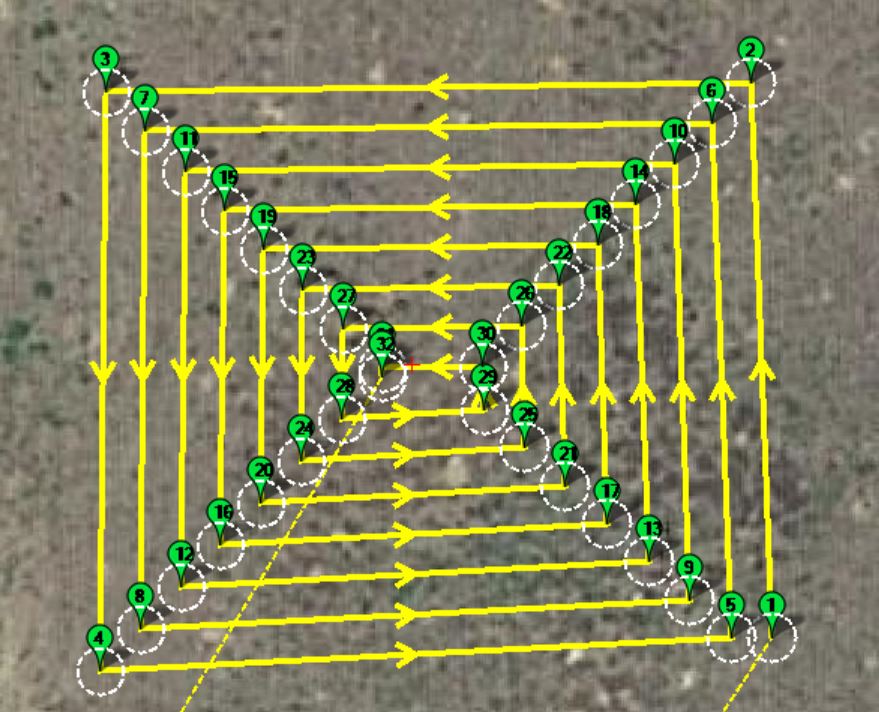
I’ve seen that but unless you see something I don’t, it creates up and back patterns. I want to go “round and round” so to speak. Mine creates what you see here:
1 Like
I drew waypoints 1,2, 3 and 4 in Mission Planner and then ran my program. You specify whether you want to go clockwise or counterclockwise and the distance you want to move in each pass. I looked hard for something like that and could not find it. I posted a question here also and have had no response. I will reply to my own post and link it here when I get this completely ready. It works with any polygon, although not perfectly for really odd shapes.
4 Likes
Kenny,
Looks good! Yes, I’m sure that none of the ground stations can do this at the moment at least. very nice.
Your program looks nice @ktrussell. I looked around for something like this as well and was not successful. I would like both options as back and forth and circular. I was able to get mission planner to do it with the survey grid and setting the camera settings to a very low altitude. But in some cases a circle is more efficient for the mower. I struggle with the maximum zoom setting allowed in MP as the points get very close together and I can’t zoom in anymore to make adjustments. I am looking forward to your program! The next feature that I would really love is to have a negative polygon inside a larger polygon that the rover would avoid when generating the paths.
1 Like