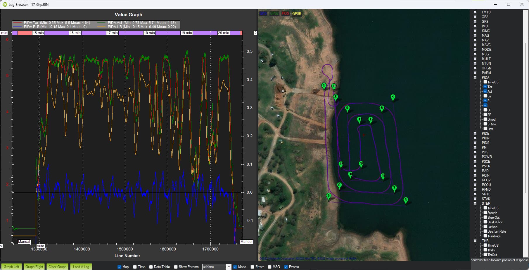
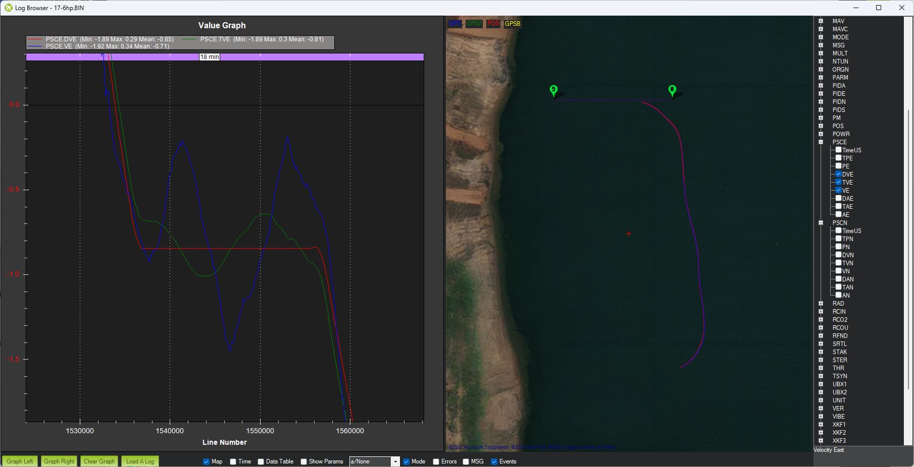
The page includes a section on setting up real-time monitoring of the velocity controller’s PID (desired, achieved, P, I, D outputs) and I think this might be useful in tuning. The only limitation is that the mission needs to be setup to be aligned North-South or West-East… and if the mission is a rectangle then the PID outputs will only be useful as the vehicle moves along two (of the four) sides.
Weight and Speed is definitely a major contributor to the performance of the controller in my opinion.
As a human, we drive very differently depending on the load we are carrying, this has to apply to a machine as well.
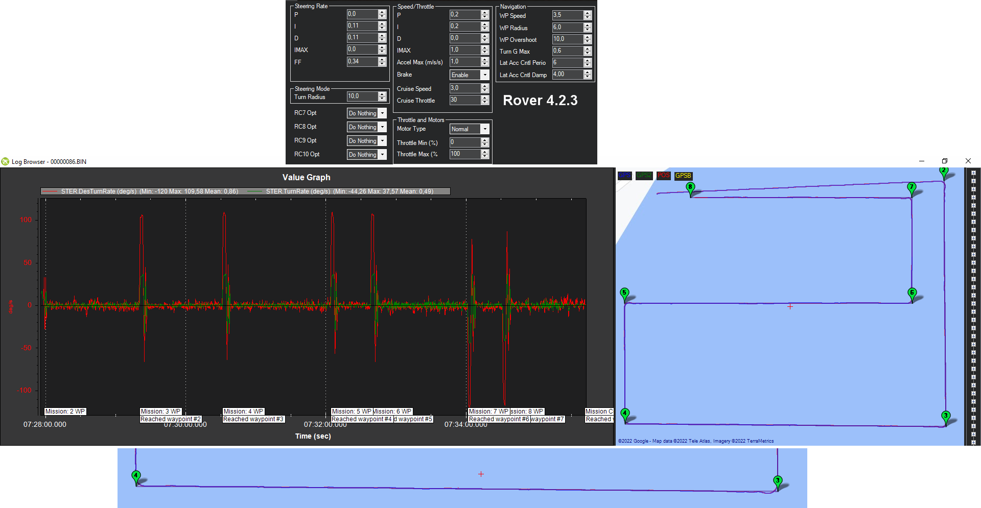
Then I changed to a larger 6hp motor with 100kg ballast with 15L fuel and as you can see it is a completely different animal once again with the original Randy settings and unfortunately nowhere near where it needs to be.
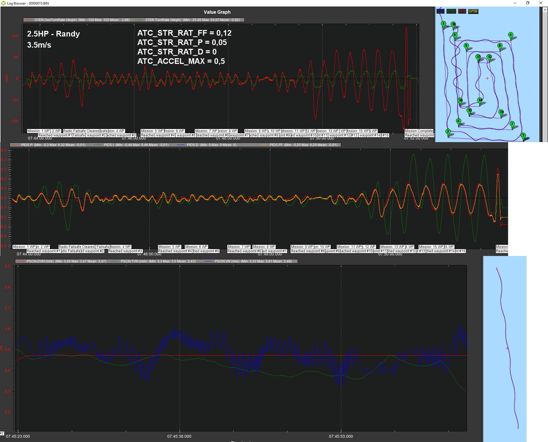
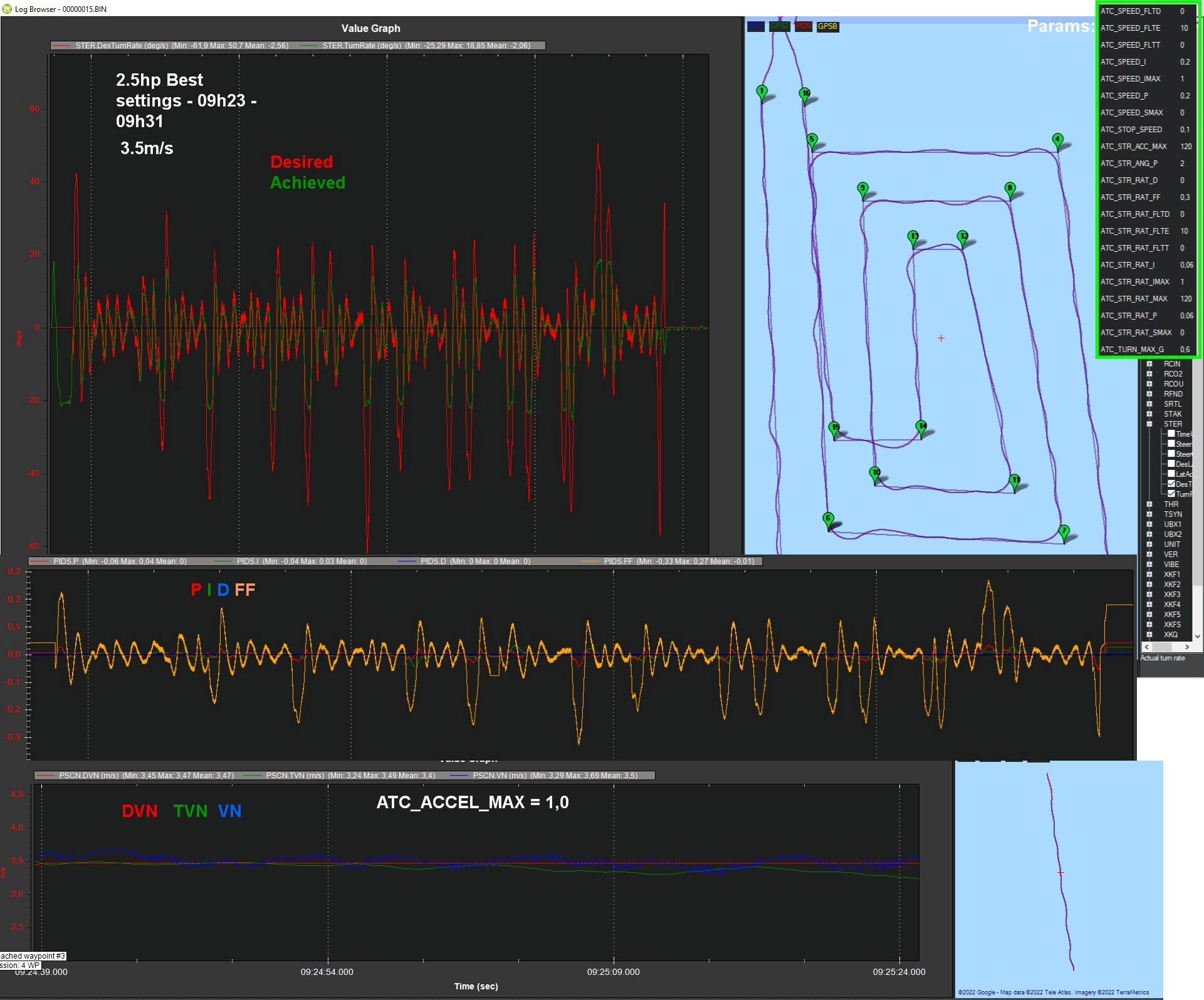
Thanks for the pics. If there’s an accompanying log or two that would be great but in any case, from the top set of pictures it looks like the vehicle basically can’t turn faster than 20deg/sec. I suspect there is some physical reason for this limit so we just need to make the system (e.g. navigation controller + turn rate controller) operate within this limit.
I think the best way to do this is to reduce WP_ACCEL even lower. I think we should consider trying incredibly low values as WP_ACCEL = 0.1 to see what happens. the vehicle will be painfully slow to accelerate up to full speed but maybe Leonard and I can resolve this issue separately.
When the higher level navigation controller asks the turn rate controller for more than 20deg/sec, it can’t achieve it and all we get is I-term build up (see the red line in the very top graph) but it doesn’t appear to help and just leads to an oscillation. Increasing the I term may help so perhaps try increasing ATC_STR_RAT_I from 0.06 to 0.2 (to match ATC_STR_RAT_P).
By the way, for the navigation controller PID output, there is PSCN_xxx (North/South) and PSCE (East-West). What we’re interested in is the direction that is perpendicular to the direction the vehicle is moving because this turns into the steering turn rate which is where the wobble is coming from. So in the tests above it looks like the vehicle is moving north-south… so we would want to look at the PSCE_xx graphs.
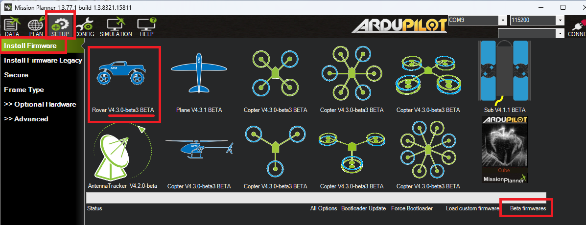
I see this autopilot is running an older version of 4.3.0-dev from 13-Jun-2022. It would be good to upgrade to the latest beta. I’m not saying this is the cause of issues but upgrading is easy and ensures we are all on the same software.
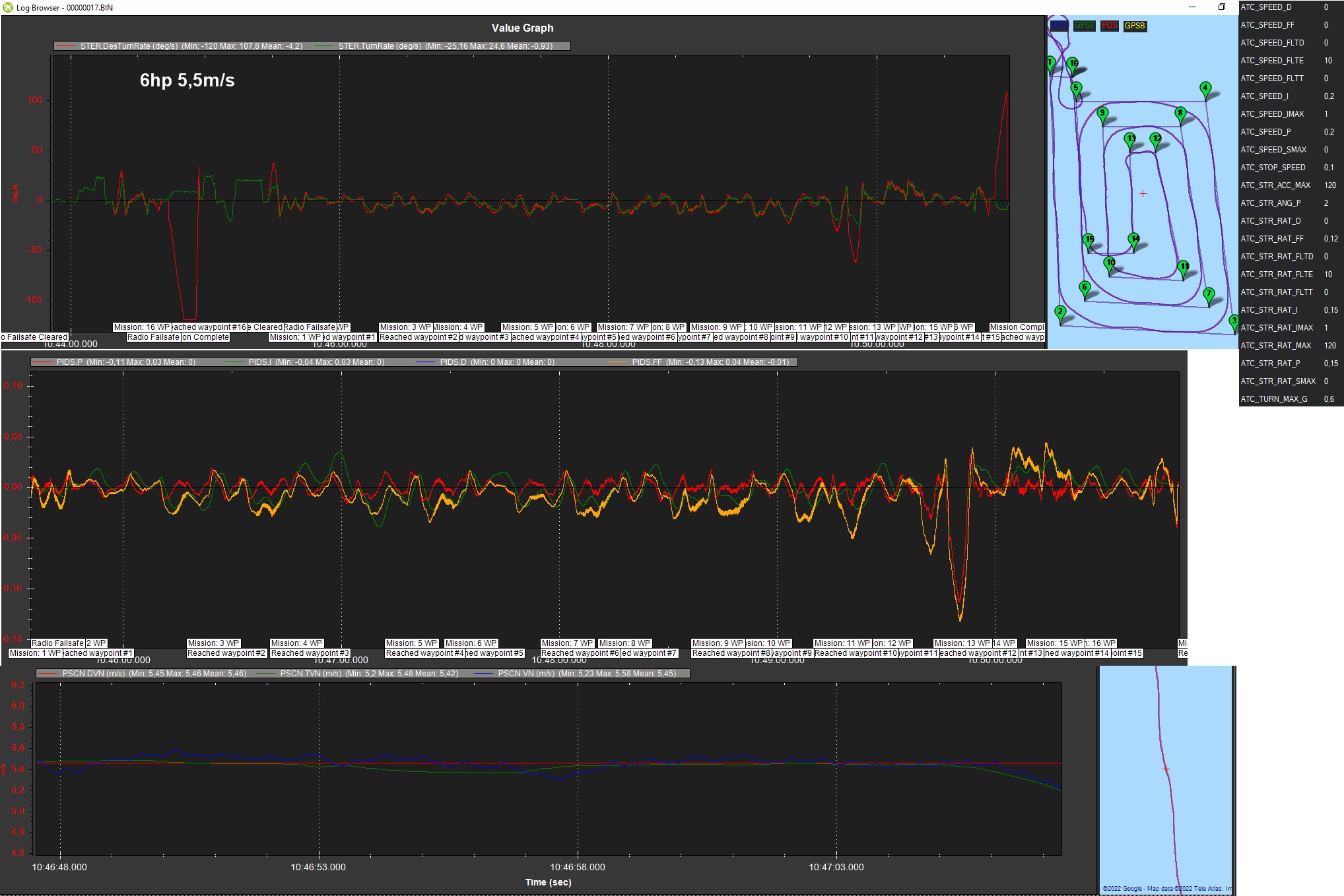
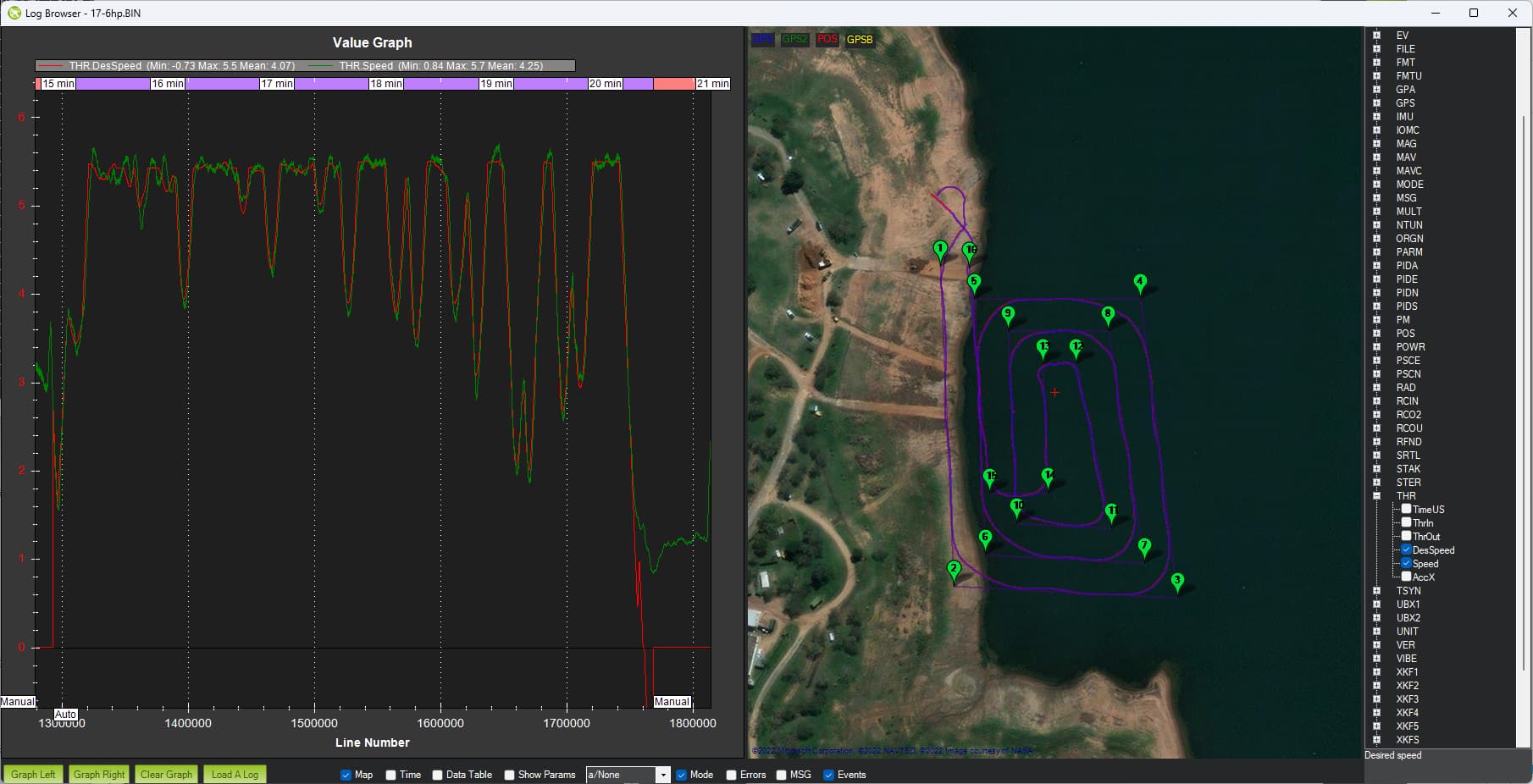
The 6hp log looks pretty good actually although there are some improvements we can make…
CRUISE_THROTTLE and CRUISE_SPEED seem to be set to zero which means the speed controller’s I-term is doing most of the work which can lead to oscillations in throttle. I think it would be good to set CRUISE_THROTTLE=50, CRUISE_SPEED=5.
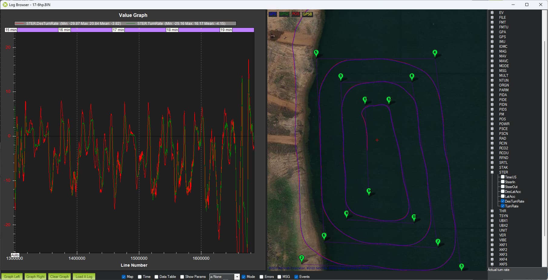
The steering turn rate controller is also working pretty well although it is slightly under performing. E.g. the actual turn rate in green does not reach the desired turn rate in red.
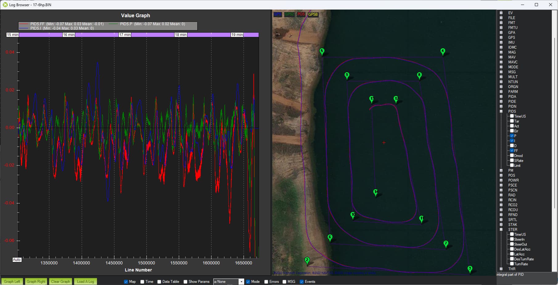
Looking at the steering PIDs it looks like the I is working a little too hard (its output is often higher than FF and P) which probably means the ATC_STR_RAT_FF should be raised from 0.12 to maybe 0.14.
Finally we get to the position controller’s mid-level velocity control and this is probably the part that needs the most improvement. If we look at the PSCE.DVE, TVE, VE then we see the actual velocity (PSCE.VE) is oscillating and not following the desired velocity (in red, PSCE.DVE) very well.
Rover 4.3 Firmware - I will do that today CRUISE TH/SP - not sure how that went back to zero as I did a LEARN CRUISE some time back, thanks for spotting that. I will change to - CRUISE_THROTTLE=50, CRUISE_SPEED=5 ATC_STR_RAT_FF - will be raised from 0.12 to maybe 0.14. PSC_VEL_P, I and D gains. - I will make the following changes
PSC_VEL_P = 2 (was 1)
PSC_VEL_I = 0.4 (was 0.2)
PSC_VEL_D = 0.2 (was 0.1)
Thank you very much for your help as always. I’m hoping to get to the dam for water testing this weekend.
Thanks. I will add a little section to the Rover Navigation tuning wiki page to explain how to look at the logs to help with tuning.
PSCN.DVN (“Desired Velocity North”) is the desired velocity from the S-Curve path. The S-Curve path provides the continuous ideal position, velocity and acceleration required to follow the path
PSCN.TVN (“Target Velocity North”) is the total velocity including the above “Desired Velocity” and also the desired velocity resulting from the position error.
PSCN.VN (“Velocity North”) is the actual velocity
The use of “desired” and “target” is a bit confusing but in general we use the word “desired” to mean a higher level target… normally from a pilot or autopilot. In this case it’s from the higher level S-Curve path planner. “target” is a lower level target… this time it’s the total target velocity which includes the velocity target from S-Curves and the target velocity resulting from the position controller’s position error correction layer. In this layer the current position error (in meters) is multiplied by PSC_POS_P param value resulting in a target velocity.
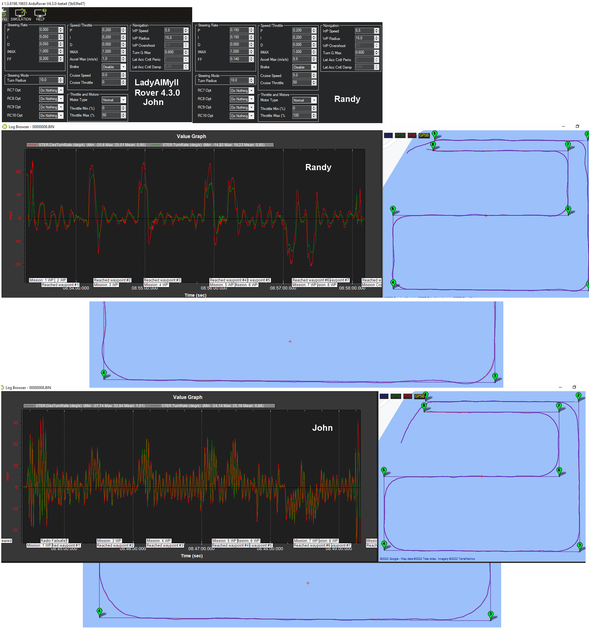
At last I got a gap to get on the water yesterday with some interesting results.
I took both the 3 meter (AIMy SKII / Rover 4.2) and 4 meter (LadyAIMyII / Rover 4.3) so I could do a test between the two.
For some strange reason I was getting a relatively low satellite count of 9-10 but the results were still quite good.
Here is a short video of the location where I was testing yesterday -
AIMy SKII -
This is what we get on a very basic right angle turns mission, ‘contouring’ a shoreline gets a little more ‘messy’ but not bad.
LadyAIMYII - LOG - Dropbox - File Deleted - Simplify your life
She snakes quite violently when first changing to Auto, but once she has found her path she calms down. There was definitely an improvement using Randy’s last settings over mine but I really hope we can get a little closer to the path tracking of 4.2 -
From previous post -
" Rover 4.3 Firmware - I will do that today CRUISE TH/SP - not sure how that went back to zero as I did a LEARN CRUISE some time back, thanks for spotting that. I will change to - CRUISE_THROTTLE=50, CRUISE_SPEED=5 ATC_STR_RAT_FF - will be raised from 0.12 to maybe 0.14. PSC_VEL_P, I and D gains. - I will make the following changes
PSC_VEL_P = 2 (was 1)
PSC_VEL_I = 0.4 (was 0.2)
PSC_VEL_D = 0.2 (was 0.1)"
In this test there are 4 pivot turns and 2 S-curves. It seems to me that when the rover comes out of an s-curve turn, if it isn’t exactly on the track from WP to WP, it doesn’t get back on that track, and instead remains on one side of the track until the next WP. Is there a parameter I should focus on to cause the rover to reduce xtrack error to 0 along the way?
I got to say that I have read this post many times and it has been very helpful to me. First of all, thanks.
I tried ackerman rover and sliding rover with V4.4 beta.Ackerman rover works well.But I meet two problems on sliding rover.
1.When a sliding vehicle is driving in a straight line on farmland or uneven roads, it is easy for the vehicle to deviate from the original straight line and the driving trajectory becomes a wavy curve. To solve this problem, which or which parameters are related?
2.Also, for sliding vehicles with varying load weights, I don’t know if anyone has ever tried to suddenly add a load weight to a unloaded vehicle that has already been well tuned for driving performance (such as placing heavy goods like 50kg or 100kg on the roof , of course the physical properties of the vehicle itself can bear this weight). Will the driving performance of the vehicle deteriorate and then most of the driving parameters need to be readjusted?(such as atc_str… related parameters, as the static and dynamic friction between the wheels on the ground have changed as the vehicle weight increases)? Because I have roughly adjusted the parameters of the sliding vehicle (unloaded), I suddenly thought of the above two questions, so I am asking this question
I’d start with the turn rate controller’s FF gain which is the most important. There are details on that page linked above on how to do this in real-time.
What I want to express in my first question is that the sliding rover has been tuned to drive well on flat ground. It travels in a straight line from flat ground to uneven ground (such as driving from the road to farmland or mud). The sliding rover should keep driving in a straight line, but when it reached uneven ground, its trajectory becomed a wavy line. Have you or anyone else encountered this problem? What parameters should be adjusted to solve this problem?
Is thos because of the height of the imu above the ground which when the rover tilts is being interpreted as moving off track and causing steering control unnecessarily? If so the dimension offsets can already be set to compensate for this within the existing firmware i believe
Thank you for reply.Maybe your right.But I’v tried in_pos_z and gps_pos_z on rover with -0.34m.
The effect is not obvious and the driving track still fluctuates. There is a very annoying phenomenon that after the vehicle travels from uneven ground to flat ground, the left and right wheels turn in turn.So the vehicle traveling on yaw becomes a wavy line. It’s hard to change back to a straight line for a short distance.
I think the most likely problem is the turn rate control tuning. If you post a log we can have a look but maybe it would be best to post in the Rover-4.4 category if that’s what you’re using?
It is definitely possible that a vehicle tuned on smooth flat ground might not drive very well in very different situations (very thick grass, mud, etc) where the friction level is very different and thus the motor outputs need to be very different. Let’s see how good the tuning is though before deciding.
Hi Randy,
Im on 4.2.3 and have not set any offsets for location of imu yet but it’s very noticeable with a boat on some choppy water, i dont believe its gps input as the movement isn’t large enough but when the boat is rocking back and forth on small choppy waves i can see and hear the escs oscillating when going straight into the chop and when i go sideways along the chop i see the props (air props on differential thrust) stopping and changing direction all the time as the fc rocks to the left and right. In my instance it has nothing to do with resistance of terrain etc its just noise being introduced into the position process variable due to the fc moving for and aft or left and right because of the attitude of the vessel rocking around.
I will try the offsets for z etc but i don’t really imagine this could be calculated and cancelled out quickly enough by the flight controller to provide effective dampening. I really dont know if the code is even in the fw to allow for the way position of fc moves relative to the centre of the actual vehicle, does 4.x rover calculate such things?
I tested rover again all afternoon today,didn’t install the tf card into the flight control,.So I’m sorry for can’t give you a log record. I’ll install it before the next test.
The situation is exactly as you say. Related to the magnitude of friction changes. It’s exactly the same thing I used to do with the ROS rover. This is a physical property determined by the vehicle structure and is independent of control system differences. For example, even if we use remote control to control a rover or we drive a SUV, it is also difficult to drive a straight path on uneven roads. Therefore, my suggestion is to reduce the route correction in uneven ground. I tried to reduce the turn correction and got a tolerably good result(but still needs to be optimized). But I still don’t know very clearly about the specific parameter control logic related to the turn correction ( the yaw control relationship between the upper and lower levels of the turn correction parameters) .
There are three reasons for vehicle trajectory deviation. 1. The wheels slip easily on mud or thin sand/gravel ground (into wavy lines). 2. A sharp change in the direction of the IMU (Compass) as the vehicle bumps up and down. 3.Change in vehicle load (empty and loaded.I sit the top of the rover today) I felt PID needed be readjustment when i sit on the top.
Two of the above three points are about the problem caused by friction changes.
In fact, I want to find a vehicle parameter that can be driven in most environments and adapt to various task loads(which may not be practical.It can be used more widely if it really works). Because skid rover are more reliable and have better off-road performance than Ackerman rover.
Sorry for my English.God knows how hard to me to press those words without mother language.