for some reason, mine has a few extra parameters, look:
Parameters_23_03_2021.param (17.5 KB)
used this tool to see the differences, quite useful:https://text-compare.com
but it must because yours is not cube?
That and it’s a 1Mb Pixhawk so missing some features.
Hello, so I did some voltage measuring and this are the results:
Whether I power the rail or not, when the relay is not connected, the aux5 gives 3.25 v High and 0.02 Low
Whether I power the rail or not, when the relay is coonected, aux5 gives ~3.8v High and ~1.3Low
Why does this happens when the relay is connected?
1 Like
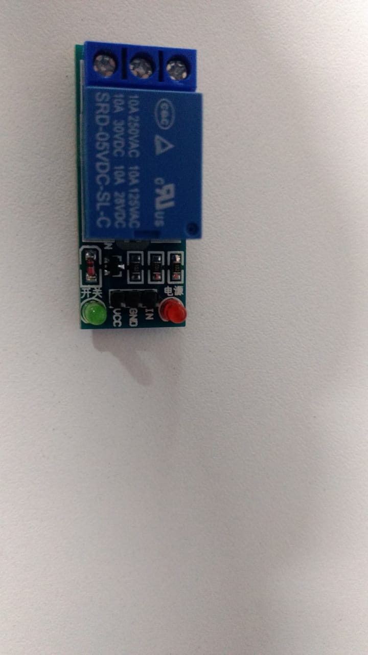
What relay are you using?
Fit a 1k pull-down resistor, maybe the relay board has a fet input that is very high input impedance.
EDIT: I mean fit it across the IN and GND
I tested right now the diode with my multimeter, it seems it’s faulty ,both ways give 0.077
The diode will be across the coil, you wont be able to measure it in-circuit.
If the relay pulls in (operates) then the diode is not shorted. If it was open circuit then you’d get problems with other dead semiconductors from the spikes.
wait , shouldn’t I be able to test it using the diode mode from a multimeter when the circuit is off?
Looks like a 5V coil to me.
Yeah I immediately thought 5vdc coil too, but on the board it’s got a Vcc input for 5 vdc and some sort of basic transistor or FET circuit to do the level shifting. A lot of these boards and similar ones list the switching input as 3.3v to 5v.
Not when it’s across a coil - essentially a long thin piece of wire.
I think that’s a good clue (Vcc input) 
It has a 2ty transistor and a zener diode if I am looking correctly