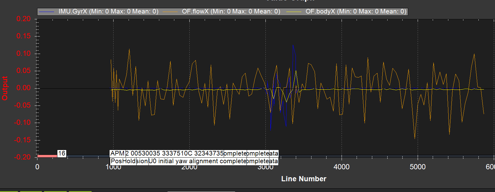
So I modified the FLOW_FYSCALER only to 100, and then I get the following, which looks like it’s getting there. But I don’t know why both X and Y axis have changed scale since FLOW_FXSCALER is still 0.
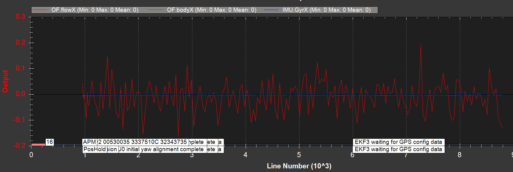
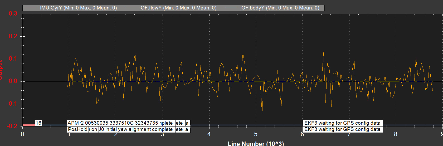
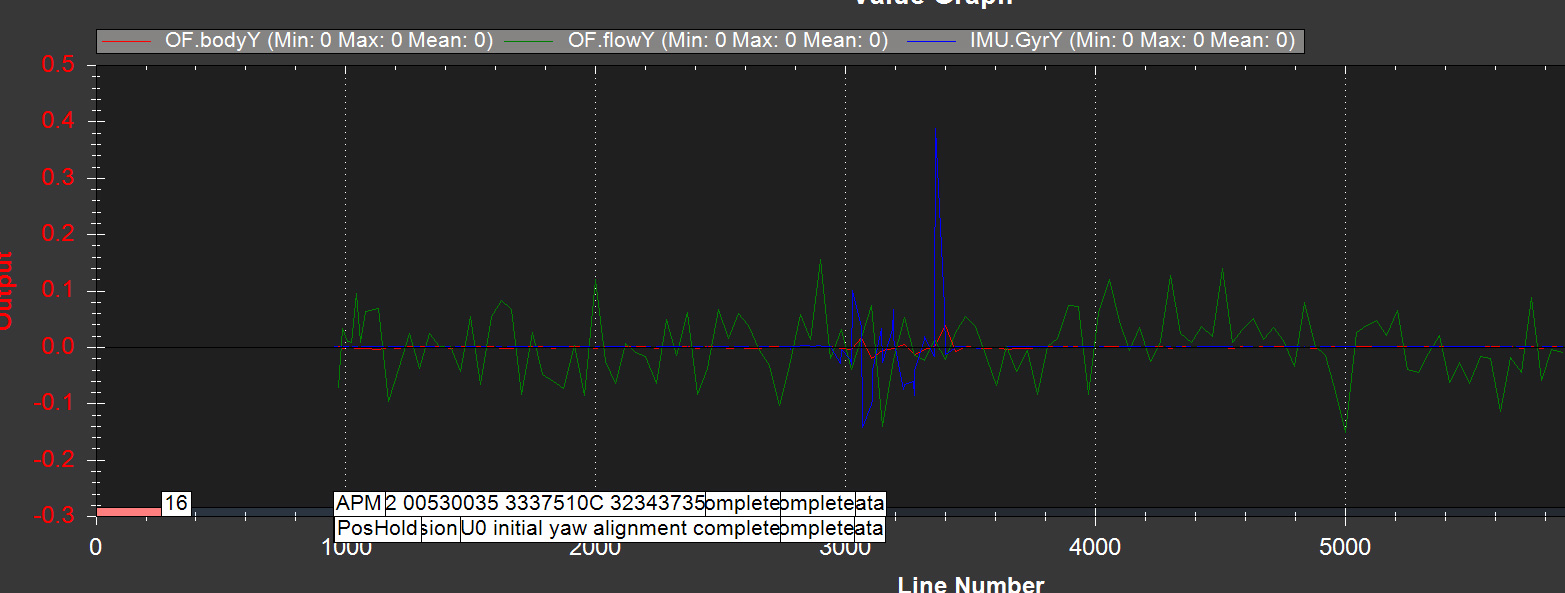
So then I changed the Y scaler to 200, and I get this. Again I don’t know why both axis have changed scale since FLOW_FXSCALER is still 0. Plus there’s some other weird Gyro stuff going on and the results just look random.
In all the tests I get: “Test: OpticalFlow = FAIL - FAIL: insufficient roll data pointsa” in the auto analysis, but I can definitely see opt_m_X and opt_m_y being non-zero and changing values as I move the drone around. I’m powering the flight controller and PX4FLOW from mt PC’s USB port during all the tests.
It is certainly possible to set the EKF origin in a GPS denied environment when using the EKF2. I did it during the recent indoor test with Rover that’s on my youtube channel.
I had a look at the logs and I guess there’s currently no lidar attached to the vehicle? The optical flow will work in FlowHold mode without a lidar but not in other modes like Loiter.
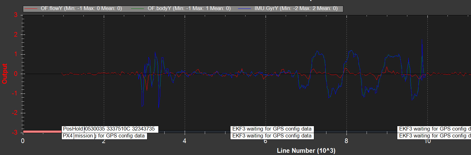
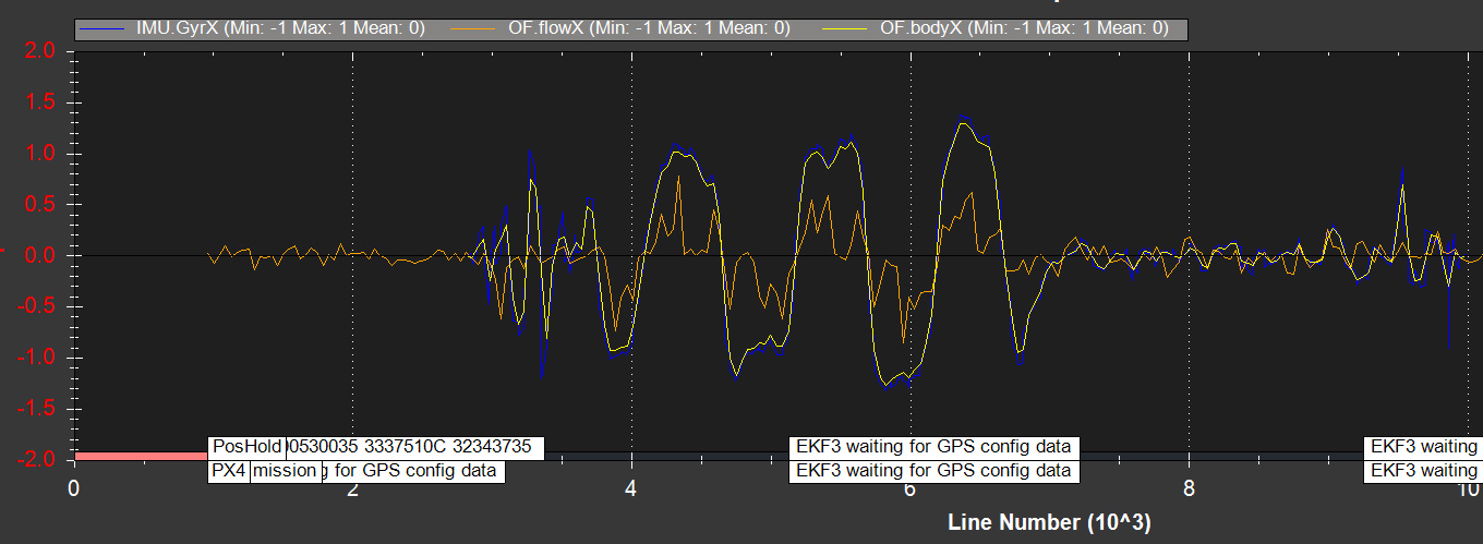
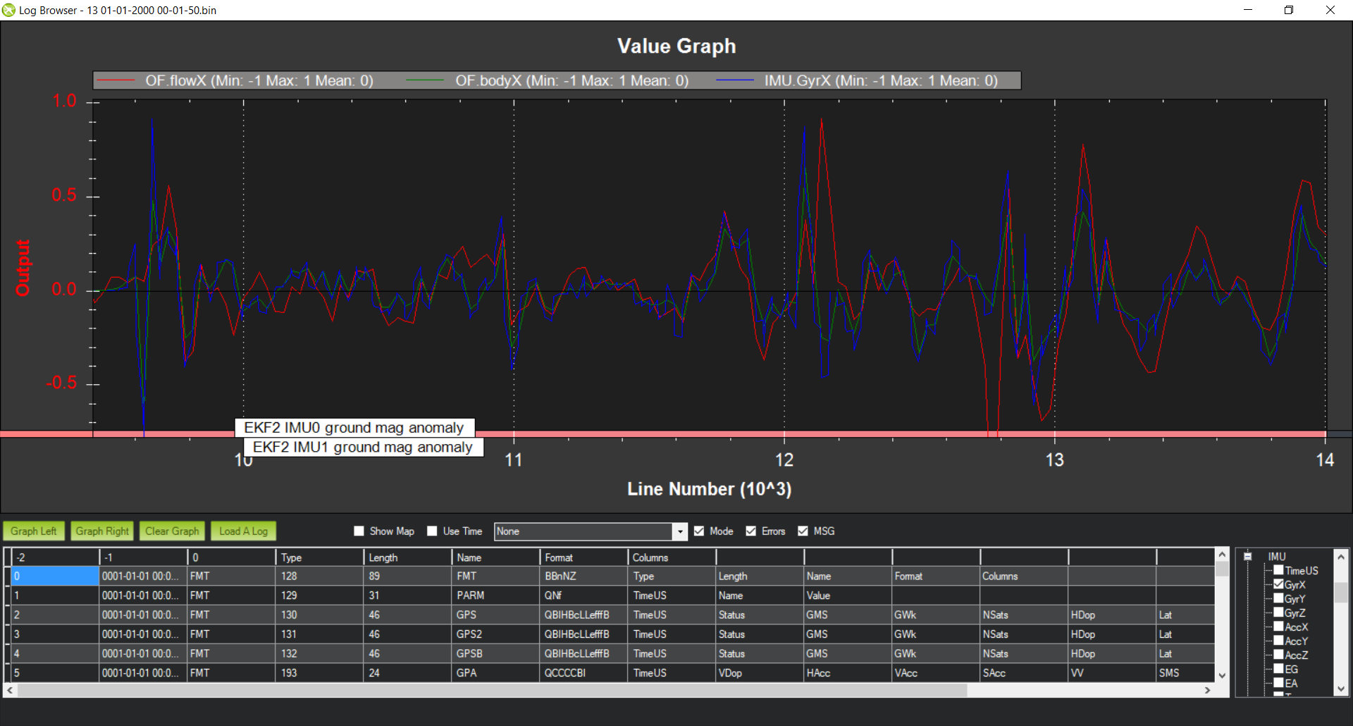
Here’s a graph of the FlowRate (i.e. raw sensor values), the BodyRate (portion of the flow which is caused by the vehicle’s rotation) and the gyro rate… all for the x-axis. It doesn’t look bad to me actually.
I guess though that I’ve got out-of-date logs from you because I see in your screen-shot above that AP is using the EKF3 but in these logs it’s back on EKF2. I think it’s fine to stick with EKF2 by the way.
I wouldn’t worry too much about the message from the auto analysis. It’s possible that it’s out of date.
Anyway, I’m not saying there’s no problem of course… just that I don’t immediatley see it in the logs I have. If you have newer logs you can post, I’ll try and review them with less delay than it took this time!
Thanks Ollie, I think the logs you have are from the default settings before I changed to EKF3 as per the other post above. In my later tests though it looks like the data was completely weird and the scaling wasn’t working, so I thought maybe the clone flight controller was doing something weird.
However, I’m now having trouble getting any of the sensors on the i2c bus to work or be seen at all. It has three i2c ports - one has the GPS plugged in which is required because the safety switch and LED are part of it. Then it has two other i2c ports labelled A and B. The A port has 4 wires and the B port has 6 wires because the UART is included in this connector. There’s a 4-wire i2c breakout/bus board included for attaching multiple i2c devices but that will only connect to the A port.
I’ve actually tried a custom cable for the B port as well but not even my sonar is seen by Ardupilot when it’s just connected to either port by itself (optical flow doesn’t work either). Any ideas which i2c ports are scanned/used by Ardupilot or how I enable them, or should I just hack into the i2c bus connected to the GPS?
It should be just a matter of plugging a device in and it is seen and used.
Have never had to actually activate any I2C devices, although for the OLED display I did have to put in what type of display it was (there are a couple of driver chips).
For I2C I have found a few issues, depending on how many devices are connected.
ID conflicts, putting 2 devices on the same bus with the same ID really screws things up.
Cable lengths can have a big impact so I now twist all I2C cables.
Breakout boards have given me big headaches in producing erratic behaviour as some chinesium ones are prone to partial failure. Was very time consuming to debug that one.
Again, depending on the number of devices, I am careful about how much power is required to drive all the I2C devices on the bus and these days provide seperate power for the bus.
Yes, they are not seen though. They are the only devices on the bus so there is no address conflict, and they both worked on the other flight controller with the same cables - I’ve just soldered the same wires to a single connector and plugged them in one by one.
So my questions is still: which i2c busses out of the three on the Pixhawk 4 are scanned/initialised by the firmware? They are labelled i2c 2, 4 and 1. I’ve attached the pinout diagram.
Hi,
I think the optical flow attached to my copter isn’t working. While I don’t get the bad OptFlow error, logs show BodyX and BodyY are constantly 0. I also currently have both FLOW_FXSCALER and FLOW_FYSCALER set to their maximum values to 200 to try and get better values. I have attached two log files for reference.
Any ideas or help would be greatly appreciated.
Thanks.