Chris - I love the paper you wrote on path planning and optimisation. Much to think about.
Re obstacles, im thinking about monitoring vibration levels on theh mower - running over branches should generate a stop rather than push on through…
1 Like
(I didn’t write the paper… I just used it as the basis for my path planner)
I think the h_acc approach would be worth pursuing, but I have been very happy with just stopping when I lose RTK Fix, as Yuri says.
@Yuri_Rage’s TerrainDetector script might be a good start on using vibration levels to take some action. It has been a big help when I am mowing in rough terrain. It slows the ground speed when rough terrain is detected.
1 Like
Is path planning better compared to the Survey Grid from the MP? Did you build a custom software for it?
Survey Grid in mission planner is quite good (as is the spiral pattern). We used it a lot, including manually editing the generated paths to mow around obstacles.
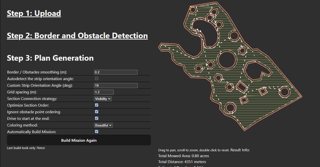
Ultimately, however, we needed to automatically (i.e. quickly) generate a path for a property, including mowing around obstacles, so we built custom software to do this. (We actually generate several for each property with different strip headings, because we learned that mowing the exact same path week after week creates ruts in the grass). While we were at it we implemented a double-wide strip around the perimeter, a double-wide strip around each obstacle, and automatic repositioning from region to region. We’re satisfied with the results, although the paths it generates aren’t quite as efficient as doing it by hand. Here’s a screenshot of our custom path builder:
Chris,
if I may ask, are you generating regular *.waypoints file for the ardrurover with your custom software or generated path can be formatted & fed to the autopilot in some other data structure? Are there any autopilot limitations related to the number of waypoints?
Our companion computer sends waypoints to the autopilot using mavlink messages… It sends 100 waypoints at a time. The companion computer receives waypoint lists from a master controller program running in the cloud, which is where the master database of the missions is stored.
You could call your custom path planner something like Terra Rover Obstacle Navigation , to go with your Master Control Program ![]()
Seriously though, that path planner looks great!
1 Like
I know it’s probably central to your business model, but I’m sure we’d all love to see an open source implementation of that planner, @Christopher_Milner. Zero pressure intended, of course. Excellent work, regardless!
2 Likes
I think what Chris has done with the custom path builder is what many would like to see in the GCS to route around known obstacles in the planning stages. Looks like it would be a lot of work to implement, but would be a big addition for the Rover people for sure.
1 Like
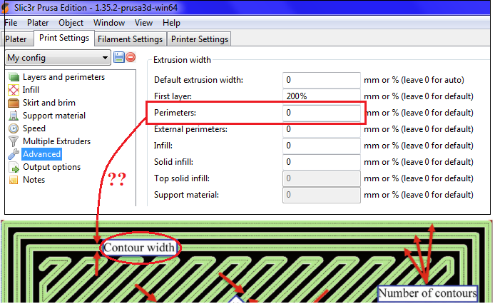
is the “flight path” for mowing a field/padock the same path generation problem as say 3d printing. Are there open source printing packages that solve this problem that we can utilise? Slic3r?. Seems to me, i just want to “print” my lawns, minimising head travel, and with a fill pattern and turn values that correspond to my printer. In some ways its an easier problem, as its just a single layer print, and no melted plastic involved.
3 Likes
I saw on an indicator light system indicating mower arming status on @Swebre mower when we were at MowStock. I thought that it was a really good idea. He had a light on his mower that would turn on when the mower was armed and turn off when it was un armed. This way just at a glance (even from a distance you could visually tell if it was armed). In the real world out in the field with a mower, the computer screen is not always available. I was thinking about doing the same thing just to add a level of safety and I started to realize it’s not straight forward (at least to me). How do I get the right signal from the FC to let me control a relay switching on a light indicating the system is armed?
I just wired one in series with my ignition circuit. When the ignition relay is hot, an amber flasher is on.
Not the same as armed, but close enough for my taste.
If you truly want an armed indication on a relay, you’ll probably need a Lua script.
1 Like
3D printed layer coverage and mowing path coverage are essentially identical problems. It could be very interesting to scale a yard to mm in lat/lng and use a slicer to directly “print” the fill pattern. A pure cartesian interpretation of lat/lng would be perfectly adequate across a few acres if scaled properly.
It’s really just my first full season of mowing with my mower and I have just been working out my mode of operation as I go along. Currently I control engine throttle, deck blade clutch, arming/disarming, mode control, emergency kill switch, and manual driving from the RC transmitter. When I stop the mower to look at something, I turn off the blades, switch to manual, throttle down the engine, and I disarm the mower if the engine is still idling before I walk up and lay hands on the mower. Usually the engine is still carrying a lot of heat and I leave it idling. I just just like knowing it is disarmed in case I bump a joystick or some other SW on the RC controller while I am standing next to the mower. Seeing an indicator light go off would give me a visual indicator that in fact I did disarm the electronics.
I could probably trigger an indicator light on and off related to me moving the arm/disarm switch on the RC transmitter, but if I happen the arm it from Mission Planner it would not trigger the indicator light. Maybe I will have to figure out a Lua script.
This paper A novel solution with rapid Voronoi-based coverage path planning in irregular environment for robotic mowing systems | SpringerLink lays out the algorithm pretty well. We read this paper carefully and started coding, and ended up with something pretty functional. Our implementation doesn’t 100% match the algorithm described in the paper but it’s quite close; we didn’t use the voroni points exactly as described.
2 Likes
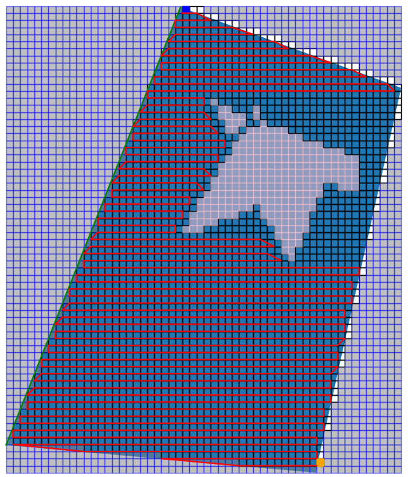
That’s an interesting paper, based on it started drafting some path planning algorithm in python, just to see the efforts it takes. And it surely took a while getting at least to the point when it can generate a path and avoid obstacles. But that’s only for me - not a developer.
It still needs some additional logic
*filling-in the gaps behind the obstacles;
*changing the mowing directions to avoid taking the same route over and over again;
*making a few inner circles around the boundaries
Although such zigzag pattern is more suitable to the smaller mowers, rather than tractors.
I would like to see some path planning with obstacle avoidance logic for the mowing in spirals, but couldn’t find any.
Kenny are you using Bendy Ruler to mow around obstacles on a routine basis now? I am just curious to find out how well it works. I would be great to just be able to declare obstacles, lay out the outer perimeter, and then fill the whole thing in with one big spiral grid pattern. Is it reliable? Is the triangle created in front of the obstacle the same shape as the one behind the obstacle?
@Christopher_Milner Did you use a map API to develop around for your custom path planning or did you develop from the ground up? White Paper you linked to was very informative. I have dug around some different map APIs and found some interesting code using Google Maps API. Just wanted to see if you could give a point in the right direction using your experience. Would love to be able to develop different mow patterns using a set of known obstacles rather than having to fix them manually with every pattern change or change in lawn that adds new obstacles. Thanks for your insights!