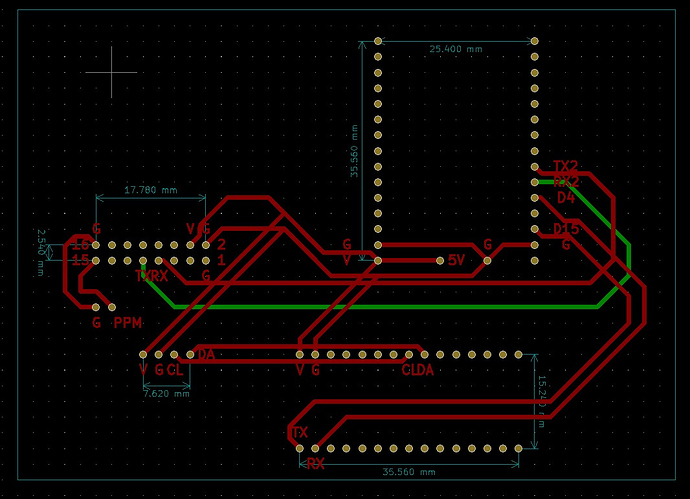
Please Ignore the shorted lines. They are not meant to be shorted. New to PCB software hence cant draw them properly.
Top Left side is RFD900x. TOP Right is an ESP32 Dev Module. Please take care of pinout if using any other board. Different versions are available which have different pinouts.
Left Middle is input for ground and PPM from any PPM capable device. Below that is an OLED panel.
Bottom Right is an arduino nano. the CL and DA connections on the arduino are meant to move one pin to the left from the reader’s perspective.
Code for Arduino Nano is as below: (I am not so good at writing code, hence I copied from somewhere and tinkered with it)
#include <Wire.h>
#include “SSD1306Ascii.h”
#include “SSD1306AsciiWire.h”
#include <mavlink.h>
#include <EEPROM.h>
#define I2C_ADDRESS 0x3C
#define RST_PIN -1
SSD1306AsciiWire oled;
#define MAV_TIMEOUT 5000 // mavlink timeout
#define SERIAL_SPEED 115200 // 9600 for sbus, 57600 for cppm
#define DEBUG
mavlink_message_t msg;
mavlink_status_t status;
// mavlink_global_position
int32_t alt, relative_alt;
int16_t vx, vy, vz;
uint16_t hdg;
// __ mavlink_sys_status_t
int8_t battery_remaining;
uint16_t current_battery, voltage_battery, cpu_load, drop_rate_comm;
// mavlink_gps_raw_int_t
int32_t lat, lon, gps_alt;
uint8_t satellites_visible, fix_type;
uint16_t cog, vel;
// oth
uint8_t flag, eeprom_flag;
uint32_t time_flag;
// ------------------------------------------------------------------------------
void setup () {
Wire.begin ();
Wire.setClock (400000L);
oled.begin (& Adafruit128x32, I2C_ADDRESS);
display_wait ();
//
Serial.begin (SERIAL_SPEED);
//
time_flag = millis ();
}
// ------------------------------------------------------------------------------
void loop () {
while (Serial.available ()) {
uint8_t c = Serial.read ();
if (mavlink_parse_char (MAVLINK_COMM_0, c, & msg, & status)) {
flag = 0;
switch (msg.msgid) {
case MAVLINK_MSG_ID_HEARTBEAT: {
break;
}
case MAVLINK_MSG_ID_GLOBAL_POSITION_INT: {
mavlink_global_position_int_t packet;
mavlink_msg_global_position_int_decode (& msg, & packet);
if (packet.hdg == 65535) packet.hdg = 0;
// if (lat!= packet.lat) {lat = packet.lat; set_flag (); }
// if (lon!= packet.lon) {lon = packet.lon; set_flag (); }
// if (alt!= packet.alt) {alt = packet.alt; set_flag (); }
if (relative_alt!= packet.relative_alt) {relative_alt = packet.relative_alt; set_flag (); }
// if (vx!= packet.vx) {vx = packet.vx; set_flag (); }
// if (vy!= packet.vy) {vy = packet.vy; set_flag (); }
// if (vz!= packet.vz) {vz = packet.vz; set_flag (); }
if (hdg!= packet.hdg) {hdg = packet.hdg; set_flag (); }
break;
}
case MAVLINK_MSG_ID_SYS_STATUS: {
__mavlink_sys_status_t packet;
mavlink_msg_sys_status_decode (& msg, & packet);
if (battery_remaining!= packet.battery_remaining && packet.battery_remaining>= 0) {battery_remaining = packet.battery_remaining; set_flag (); }
if (voltage_battery!= packet.voltage_battery && packet.voltage_battery!= 65535) {voltage_battery = packet.voltage_battery; set_flag (); }
if (current_battery!= packet.current_battery) {current_battery = packet.current_battery; set_flag (); }
if (cpu_load!= packet.load) {cpu_load = packet.load; set_flag (); }
if (drop_rate_comm!= packet.drop_rate_comm) {drop_rate_comm = packet.drop_rate_comm; set_flag (); }
break;
}
case MAVLINK_MSG_ID_ATTITUDE: {
break;
}
case MAVLINK_MSG_ID_GPS_GLOBAL_ORIGIN: {
break;
}
case MAVLINK_MSG_ID_RC_CHANNELS_RAW: {
break;
}
case MAVLINK_MSG_ID_VFR_HUD: {
break;
}
case MAVLINK_MSG_ID_GPS_RAW_INT: {
__mavlink_gps_raw_int_t packet;
mavlink_msg_gps_raw_int_decode (& msg, & packet);
if (packet.cog == 65535) packet.cog = 0;
if (packet.vel == 65535) packet.vel = 0;
if (packet.alt == 65535) packet.alt = 0;
if (lat!= packet.lat) {lat = packet.lat; set_flag (); }
if (lon!= packet.lon) {lon = packet.lon; set_flag (); }
// if (gps_alt!= packet.alt) {gps_alt = packet.alt; set_flag (); }
if (vel!= packet.vel) {vel = packet.vel; set_flag (); }
if (cog!= packet.cog) {cog = packet.cog; set_flag (); }
if (fix_type!= packet.fix_type) {fix_type = packet.fix_type; set_flag (); }
if (satellites_visible!= packet.satellites_visible) {satellites_visible = packet.satellites_visible; set_flag (); }
break;
}
default: {
#ifdef DEBUG
Serial.println (msg.msgid); // see unused packet types
#endif
break;
}
} // switch
if (flag == 1) {
display_data ();
} // print flag
else {
no_data ();
}
} // if mavlink_parse_char
} // while serial available
no_data (); // check no serial input data fuction
}
void set_flag () {
flag = 1;
eeprom_flag = 0;
time_flag = millis ();
}
void display_wait () {
oled.setFont (font8x8);
oled.set2X ();
oled.clear ();
oled.println (“WAIT FOR”);
oled.println (“MAVLINK”);
oled.set1X ();
oled.setFont (font5x7);
}
void display_data () {
oled.clear ();
printL (lat); // gps
oled.print (" “);
printL (lon);
oled.println ();
oled.println ((String) “SA:” + satellites_visible + (String) " F:” + fix_type + (String) “D L:” + cpu_load / 10 + (String) “% E:” + drop_rate_comm / 100 + (String) “%”);
oled.println ((String) “H:” + hdg + (String) " S:" + (uint8_t) (vel / 100 * 3.6) + (String) “kmh A:” + relative_alt / 1000 + (String) "m ");
oled.println ((String) “BAT:” + current_battery / 100.0 + (String) "A " + voltage_battery / 1000.0 + (String) “V R:” + battery_remaining + (String) “%”);
}
void printL (int32_t degE7) {
// Extract and print negative sign
if (degE7 <0) {
degE7 = -degE7;
oled.print (’-’);
}
// whole degrees
int32_t deg = degE7 / 10000000L;
oled.print (deg);
oled.print (’.’);
// Get fractional degrees
degE7 -= deg * 10000000L;
// Print leading zeroes, if needed
int32_t factor = 1000000L;
while ((degE7 <factor) && (factor> 1L)) {
oled.print (‘0’);
factor /= 10L;
}
// Print fractional degrees
oled.print (degE7);
}
void no_data () {
if ((millis () - time_flag)> MAV_TIMEOUT) {// no mavlink data at 2sec
#ifdef DEBUG
Serial.println ((String) “LOST MAVLINK DATA”);
#endif
display_wait ();
delay (300);
if (eeprom_flag == 0 && lat!= 0 && lon!= 0 && fix_type> 1)
{// if gps coordinates present, save it
#ifdef DEBUG
Serial.println (“save …”);
#endif
EEPROM_int32_write (5, lat);
EEPROM_int32_write (16, lon);
EEPROM.write (30, satellites_visible);
EEPROM.write (32, fix_type);
EEPROM.write (34, cpu_load);
EEPROM.write (40, drop_rate_comm);
EEPROM.write (46, hdg);
EEPROM.write (52, vel);
EEPROM_int32_write (56, relative_alt);
EEPROM.write (66, current_battery);
EEPROM.write (72, voltage_battery);
EEPROM.write (74, battery_remaining);
eeprom_flag = 1;
} else
{// no fresh data on mavlink, read from memory
#ifdef DEBUG
Serial.println (“read …”);
#endif
lat = EEPROM_int32_read (5);
lon = EEPROM_int32_read (16);
satellites_visible = EEPROM.read (30);
fix_type = EEPROM.read (32);
cpu_load = EEPROM.read (34);
drop_rate_comm = EEPROM.read (40);
hdg = EEPROM.read (46);
vel = EEPROM.read (52);
relative_alt = EEPROM_int32_read (56);
current_battery = EEPROM.read (66);
voltage_battery = EEPROM.read (72);
battery_remaining = EEPROM.read (74);
eeprom_flag = 1;
}
display_data ();
time_flag = millis ();
}
}
int32_t EEPROM_int32_read (int addr) // read from EEPROM 4 bytes unsigned long
{
byte raw [4];
for (byte i = 0; i <4; i ++) raw [i] = EEPROM.read (addr + i);
int32_t & data = (int32_t &) raw;
return data;
}
// *** *****************
void EEPROM_int32_write (int addr, int32_t data) // write to EEPROM 4 bytes unsigned long
{
byte raw [4];
(int32_t &) raw = data;
for (byte i = 0; i <4; i ++) EEPROM.write (addr + i, raw [i]);
}
The Code for ESP 32 is as below (it is a modified version of ESP32 Serial Bridge) I use only port 8881:
#include <mavlink.h>
// Disclaimer: Don’t use for life support systems
// or any other situations where system failure may affect
// user or environmental safety.
#include “config.h”
#include <esp_wifi.h>
#include <WiFi.h>
HardwareSerial Serial_one(1);
HardwareSerial Serial_two(2);
HardwareSerial* COM[NUM_COM] = {&Serial, &Serial_one , &Serial_two};
#define MAX_NMEA_CLIENTS 1
#ifdef PROTOCOL_TCP
#include <WiFiClient.h>
WiFiServer server_0(SERIAL0_TCP_PORT);
WiFiServer server_1(SERIAL1_TCP_PORT);
WiFiServer server_2(SERIAL2_TCP_PORT);
WiFiServer *server[NUM_COM]={&server_0,&server_1,&server_2};
WiFiClient TCPClient[NUM_COM][MAX_NMEA_CLIENTS];
#endif
uint8_t buf1[NUM_COM][bufferSize];
uint16_t i1[NUM_COM]={0,0,0};
uint8_t buf2[NUM_COM][bufferSize];
uint16_t i2[NUM_COM]={0,0,0};
uint8_t BTbuf[bufferSize];
uint16_t iBT =0;
void setup() {
//delay(500);
COM[0]->begin(UART_BAUD0, SERIAL_PARAM0, SERIAL0_RXPIN, SERIAL0_TXPIN);
COM[1]->begin(UART_BAUD1, SERIAL_PARAM1, SERIAL1_RXPIN, SERIAL1_TXPIN);
COM[2]->begin(UART_BAUD2, SERIAL_PARAM2, SERIAL2_RXPIN, SERIAL2_TXPIN);
if(debug) COM[DEBUG_COM]->println("\n\nHA WiFi serial bridge with MAVLINK V2.0");
#ifdef MODE_AP
if(debug) COM[DEBUG_COM]->println(“Open ESP Access Point mode”);
//AP mode (phone connects directly to ESP) (no router)
WiFi.mode(WIFI_AP);
WiFi.softAPConfig(ip, ip, netmask); // configure ip address for softAP
WiFi.softAP(ssid, pw); // configure ssid and password for softAP
#endif
#ifdef MODE_STA
if(debug) COM[DEBUG_COM]->println(“Open ESP Station mode”);
// STATION mode (ESP connects to router and gets an IP)
// Assuming phone is also connected to that router
// from RoboRemo you must connect to the IP of the ESP
WiFi.mode(WIFI_STA);
WiFi.begin(ssid, pw);
if(debug) COM[DEBUG_COM]->print(“try to Connect to Wireless network: “);
if(debug) COM[DEBUG_COM]->println(ssid);
while (WiFi.status() != WL_CONNECTED) {
//delay(500);
if(debug) COM[DEBUG_COM]->print(”.”);
}
if(debug) COM[DEBUG_COM]->println("\nWiFi connected");
#endif
#ifdef PROTOCOL_TCP
COM[1]->println(“Starting TCP Server 2”);
if(debug) COM[DEBUG_COM]->println(“Starting TCP Server 2”);
server[1]->begin(); // start TCP server
server[1]->setNoDelay(true);
#endif
esp_err_t esp_wifi_set_max_tx_power(100); //lower WiFi Power
}
void loop()
{
#ifdef PROTOCOL_TCP
if (server[1]->hasClient())
{
for(byte i = 0; i < MAX_NMEA_CLIENTS; i++){
//find free/disconnected spot
if (!TCPClient[1][i] || !TCPClient[1][i].connected()){
if(TCPClient[1][i]) TCPClient[1][i].stop();
TCPClient[1][i] = server[1]->available();
if(debug) COM[DEBUG_COM]->print(“New client for COM”);
if(debug) COM[DEBUG_COM]->print(1);
if(debug) COM[DEBUG_COM]->println(i);
continue;
}
}
//no free/disconnected spot so reject
WiFiClient TmpserverClient = server[1]->available();
TmpserverClient.stop();
}
#endif
if(COM[1] != NULL)
{
for(byte cln = 0; cln < MAX_NMEA_CLIENTS; cln++)
{
if(TCPClient[1][cln])
{
while(TCPClient[1][cln].available())
{
buf1[1][i1[1]] = TCPClient[1][cln].read(); // read char from client (LK8000 app)
if(i1[1]<bufferSize-1) i1[1]++;
}
      COM[1]->write(buf1[1], i1[1]); // now send to UART(num):
      i1[1] = 0;
    }
  }
  if(COM[1]->available())
  {
    while(COM[1]->available())
    {
      //buf2[num][i2[num]] = COM[num]->read(); // read char from UART(num)
      uint8_t c = COM[1]->read();
      buf2[1][i2[1]] = c;
      if(i2[1]<bufferSize-1) i2[1]++;
    }
    // now send to WiFi:
    for(byte cln = 0; cln < MAX_NMEA_CLIENTS; cln++)
    {
      if(TCPClient[1][cln])
        TCPClient[1][cln].write(buf2[1], i2[1]);
//-------------TEST READ FROM TWO COMS AND WRITE TO COM2 FOR ARDUINO NANO----------
COM[2]->write(buf2[1], i2[1]);
//-------------TEST READ FROM TWO COMS AND WRITE TO COM2 FOR ARDUINO NANO----------
}
i2[1] = 0;
}
}
}
The config.h file for ESP32 is as follows:
// config: ////////////////////////////////////////////////////////////
//
//#define BLUETOOTH // NO BLUETOOTH REQUIRED =>> 20191114
//#define OTA_HANDLER // NO OTA FUNCTIONALITY REQUIRED =>> 20191114
//#define MODE_AP // phone connects directly to ESP
#define MODE_STA
#define PROTOCOL_TCP
bool debug = true;
#define VERSION “1.10”
// For AP mode:
const char *ssid = “HA”; // You will connect your phone to this Access Point
const char *pw = “”; // and this is the password
//IPAddress ip(192, 168, 4, 1); // From RoboRemo app, connect to this IP
//IPAddress netmask(255, 255, 255, 0);
// You must connect the phone to this AP, then:
// menu -> connect -> Internet(TCP) -> 192.168.4.1:8880 for UART0
// -> 192.168.4.1:8881 for UART1
// -> 192.168.4.1:8882 for UART2
#define NUM_COM 3 // total number of COM Ports
#define DEBUG_COM 0 // debug output to COM0
/************************* COM Port 0 ******/
#define UART_BAUD0 115200 // Baudrate UART0
#define SERIAL_PARAM0 SERIAL_8N1 // Data/Parity/Stop UART0
#define SERIAL0_RXPIN 21 // receive Pin UART0
#define SERIAL0_TXPIN 1 // transmit Pin UART0
#define SERIAL0_TCP_PORT 8880 // Wifi Port UART0
/ COM Port 1 ******/
#define UART_BAUD1 115200 // Baudrate UART1
#define SERIAL_PARAM1 SERIAL_8N1 // Data/Parity/Stop UART1
#define SERIAL1_RXPIN 16 // receive Pin UART1
#define SERIAL1_TXPIN 17 // transmit Pin UART1
#define SERIAL1_TCP_PORT 8881 // Wifi Port UART1
/ COM Port 2 *******************************/
#define UART_BAUD2 115200 // Baudrate UART2
#define SERIAL_PARAM2 SERIAL_8N1 // Data/Parity/Stop UART2
#define SERIAL2_RXPIN 15 // receive Pin UART2
#define SERIAL2_TXPIN 4 // transmit Pin UART2
#define SERIAL2_TCP_PORT 8882 // Wifi Port UART2
#define bufferSize 4096 // Changed 2048 from 1024
//////////////////////////////////////////////////////////////////////////


