To be tested: http://mavlink.org/messages/common#PARAM_REQUEST_READ
To be checked: http://mavlink.org/messages/common#SYS_STATUS
Potential implementation of other alarms, like high intensity
You can restrict the maximum package size with this parameter in mavlink_types.h:
#ifndef MAVLINK_MAX_PAYLOAD_LEN_
// it is possible to override this, but be careful! Defa_ #define **MAVLINK_MAX_PAYLOAD_LEN 255 ///< Maximum payload length_ #endif_
*/
// In case we need a second serial port for debugging #define SOFT_SERIAL_DEBUGGING // Comment this line if no serial debugging is needed
#ifdef SOFT_SERIAL_DEBUGGING
// Library to use serial debugging with a second board #include <SoftwareSerial.h>
SoftwareSerial pxSerial(10,11); // RX, TX #endif
// Mavlink variables
unsigned long previousMillisMAVLink = 0; // will store last time MAVLink was transmitted and listened
unsigned long next_interval_MAVLink = 1000; // next interval to count
const int num_hbs = 60; // # of heartbeats to wait before activating STREAMS from Pixhawk. 60 = one minute.
int num_hbs_pasados = num_hbs;
// FastLed setup
// How many leds in your strip? #define NUM_LEDS 8 #define BRIGHTNESS 255 // Put 0 to switch off all leds
#ifdef SOFT_SERIAL_DEBUGGING
// [DEB] Soft serial port start
Serial.begin(57600);
Serial.println(“MAVLink starting.”);
pxSerial.begin(57600); #endif
}
void loop() {
// MAVLink
/* The default UART header for your MCU */
int sysid = 1; ///< ID 20 for this airplane. 1 PX, 255 ground station
int compid = 158; ///< The component sending the message
int type = MAV_TYPE_QUADROTOR; ///< This system is an airplane / fixed wing
// Define the system type, in this case an airplane → on-board controller
// uint8_t system_type = MAV_TYPE_FIXED_WING;
uint8_t system_type = MAV_TYPE_GENERIC;
uint8_t autopilot_type = MAV_AUTOPILOT_INVALID;
uint8_t system_mode = MAV_MODE_PREFLIGHT; ///< Booting up
uint32_t custom_mode = 0; ///< Custom mode, can be defined by user/adopter
uint8_t system_state = MAV_STATE_STANDBY; ///< System ready for flight
// Initialize the required buffers
mavlink_message_t msg;
uint8_t buf[MAVLINK_MAX_PACKET_LEN];
// Copy the message to the send buffer
uint16_t len = mavlink_msg_to_send_buffer(buf, &msg);
// Send the message with the standard UART send function
// uart0_send might be named differently depending on
// the individual microcontroller / library in use.
unsigned long currentMillisMAVLink = millis();
if (currentMillisMAVLink - previousMillisMAVLink >= next_interval_MAVLink) {
// Guardamos la última vez que se cambió el modo
previousMillisMAVLink = currentMillisMAVLink;
MAV_DATA_STREAM_EXTRA1=10, /* Dependent on the autopilot
MAV_DATA_STREAM_EXTRA2=11, /* Dependent on the autopilot
MAV_DATA_STREAM_EXTRA3=12, /* Dependent on the autopilot
MAV_DATA_STREAM_ENUM_END=13,
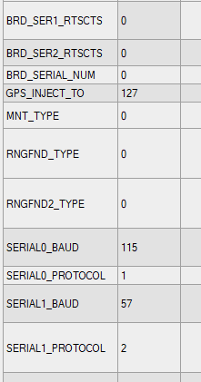
Data in PixHawk available in:
Battery, amperage and voltage (SYS_STATUS) in MAV_DATA_STREAM_EXTENDED_STATUS
Gyro info (IMU_SCALED) in MAV_DATA_STREAM_EXTRA1
*/
// To be setup according to the needed information to be requested from the Pixhawk
const int maxStreams = 2;
const uint8_t MAVStreams[maxStreams] = {MAV_DATA_STREAM_EXTENDED_STATUS, MAV_DATA_STREAM_EXTRA1};
const uint16_t MAVRates[maxStreams] = {0x02,0x05};
// Echo for manual debugging
// Serial.println(“—Start—”);
#ifdef SOFT_SERIAL_DEBUGGING
while(pxSerial.available()>0) {
uint8_t c = pxSerial.read(); #else
while(Serial.available()>0) {
uint8_t c = Serial.read(); #endif
// Try to get a new message
if(mavlink_parse_char(MAVLINK_COMM_0, c, &msg, &status)) {
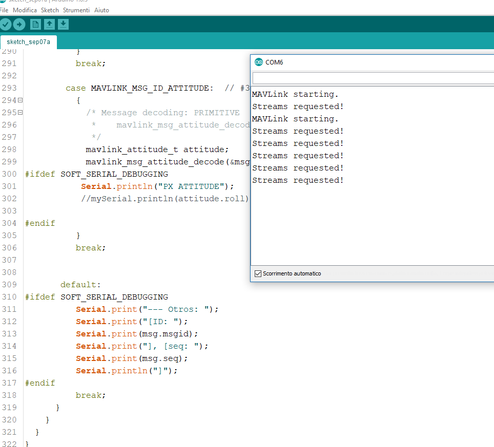
// Handle message
switch(msg.msgid) {
case MAVLINK_MSG_ID_HEARTBEAT: // #0: Heartbeat
{
// E.g. read GCS heartbeat and go into
// comm lost mode if timer times out
Small updat;e. now seems to work (with only logic level converter) but if the tx (tx arduino rx minipixhawk) disconneted. if i connect it back the communication stops
Hi!
at the end was a defective connectors (when i connected the tx goes in cc). so the code is working.
thanks so much for your help… i will go head developing a code for load a mission in automatic…
bye!
Hi @jplopezll
I’m interested with your post, can i send the mavlink message to raspberry with mavproxy to forward to GCS? I plan to add some encryption in mavlink data. could you help me?
Can you please explain a bit more what is your setup and the problem you have? SoftSerial is just a library to be able to use two digital pins as a serial port. You only need to specify two pins different than the ones already hard wired with the UART of the board.
I am using SoftSerial pins to connect to the Pixhawk so that I can use the Serial Monitor of the Arduino IDE to “see” what is happening.
I’m working on a school project using arduino and a pixfalcon. @jplopezll thanks your guide I was able to read the paremeters I needed from the pixfalcon.
Now I need to set some parameters to the pixfalcon while its doing a flight plan route. I want to set the target altitude/or modify the throttle, and hopefully be able to pause the mission, move the quad a little forward and then resume the mission, the idea is to avoid some obstacles in the path of the mission. Could you provide me some guidance in this topic?
As you can read there, you will ‘just’ need to send the appropriate commands. You can see the sending process in my code when requesting the activation of streams. You need to implement when to send what command to the Pixhawk (Pixfalcon in your case). You can see the primitive definition for each command in the library.
You might need to use the full v1 of MAVLink library. You can move to v2 of MAVLink in case you have enough memory in your device.
If you need further assistance, PM me and I will try to help.
It seems I cannot edit this post any longer due to expiration of the allowed editing period.
I have asked to be allowed to regain edit permissions to correct errors and add tips and tricks. Meanwhile, I wanted to add some simplified code with SoftwareSerial enabled and just enough code to start receiving heartbeats from the Pixhawk.
#include <mavlink.h>
#include <SoftwareSerial.h>
SoftwareSerial _MavLinkSerial(9, 10); // PIN 9=Telemetry TX->Pixhawk RX, PIN 10=Telemetry RX->Pixhawk TX

// Mavlink variables
unsigned long previousMillisMAVLink = 0;     // will store last time MAVLink was transmitted and listened
unsigned long next_interval_MAVLink = 1000;  // next interval to count
const int num_hbs = 60;                      // # of heartbeats to wait before activating STREAMS from Pixhawk. 60 = one minute.
int num_hbs_pasados = num_hbs;

void setup() {
  // MAVLink interface start
  _MavLinkSerial.begin(57600);

  Serial.begin(57600);
  Serial.println("MAVLink starting.");
}

void loop() {

  // MAVLink
  /* The default UART header for your MCU */
  int sysid = 1;                   ///< ID 20 for this airplane. 1 PX, 255 ground station
  int compid = 158;                ///< The component sending the message
  int type = MAV_TYPE_QUADROTOR;   ///< This system is an airplane / fixed wing

  // Define the system type, in this case an airplane -> on-board controller
  // uint8_t system_type = MAV_TYPE_FIXED_WING;
  uint8_t system_type = MAV_TYPE_GENERIC;
  uint8_t autopilot_type = MAV_AUTOPILOT_INVALID;

  uint8_t system_mode = MAV_MODE_PREFLIGHT; ///< Booting up
  uint32_t custom_mode = 0;                 ///< Custom mode, can be defined by user/adopter
  uint8_t system_state = MAV_STATE_STANDBY; ///< System ready for flight

  // Initialize the required buffers
  mavlink_message_t msg;
  uint8_t buf[MAVLINK_MAX_PACKET_LEN];

  // Pack the message
  //mavlink_msg_heartbeat_pack(sysid,compid, &msg, type, autopilot_type, system_mode, custom_mode, system_state);
  mavlink_msg_heartbeat_pack(1, 0, &msg, type, autopilot_type, system_mode, custom_mode, system_state);

  // Copy the message to the send buffer
  uint16_t len = mavlink_msg_to_send_buffer(buf, &msg);

  // Send the message with the standard UART send function
  // uart0_send might be named differently depending on
  // the individual microcontroller / library in use.
  unsigned long currentMillisMAVLink = millis();
  if (currentMillisMAVLink - previousMillisMAVLink >= next_interval_MAVLink)
  {
    // Record last HB update
    previousMillisMAVLink = currentMillisMAVLink;


    //Mav_Request_Data();
    num_hbs_pasados++;
    if (num_hbs_pasados >= num_hbs) {
      // Request streams from Pixhawk
      Serial.println("Streams requested!");
      Mav_Request_Data();
      num_hbs_pasados = 0;
    }

  }

  // Check reception buffer
  comm_receive();
}


void Mav_Request_Data()
{
  mavlink_message_t msg;
  uint8_t buf[MAVLINK_MAX_PACKET_LEN];


  // To be setup according to the needed information to be requested from the Pixhawk
  const int  maxStreams = 1;
  const uint8_t MAVStreams[maxStreams] = {MAV_DATA_STREAM_POSITION};
  const uint16_t MAVRates[maxStreams] = {0x02};

  for (int i = 0; i < maxStreams; i++) {
    mavlink_msg_request_data_stream_pack(6, 200, &msg, 1, 0, MAVStreams[i], MAVRates[i], 1);
    uint16_t len = mavlink_msg_to_send_buffer(buf, &msg);
    _MavLinkSerial.write(buf, len);
  }
}

void comm_receive() {
  mavlink_message_t msg;
  mavlink_status_t status;

  while (_MavLinkSerial.available() > 0) {
    uint8_t c = _MavLinkSerial.read();

    // Try to get a new message
    if (mavlink_parse_char(MAVLINK_COMM_0, c, &msg, &status))
    {
      Serial.print("DEBUG msgid:"); Serial.println(msg.msgid);
      // Handle message
      switch (msg.msgid)
      {
        case MAVLINK_MSG_ID_HEARTBEAT:  // #0: Heartbeat
          {
            // E.g. read GCS heartbeat and go into
            // comm lost mode if timer times out
          }
          break;
      }
    }
  }
}
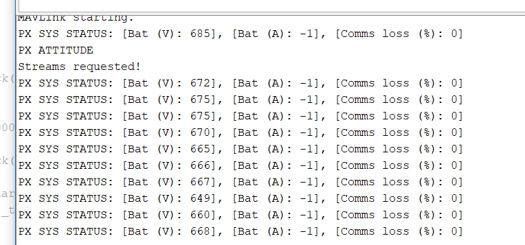
The code is commented and mostly self-explanatory. You need to power the Pixhawk from the PDB or any external power source and use the Serial Monitor of the Arduino IDE to see what’s cooking.
In case you need any further assistance, do not hesitate to contact me.
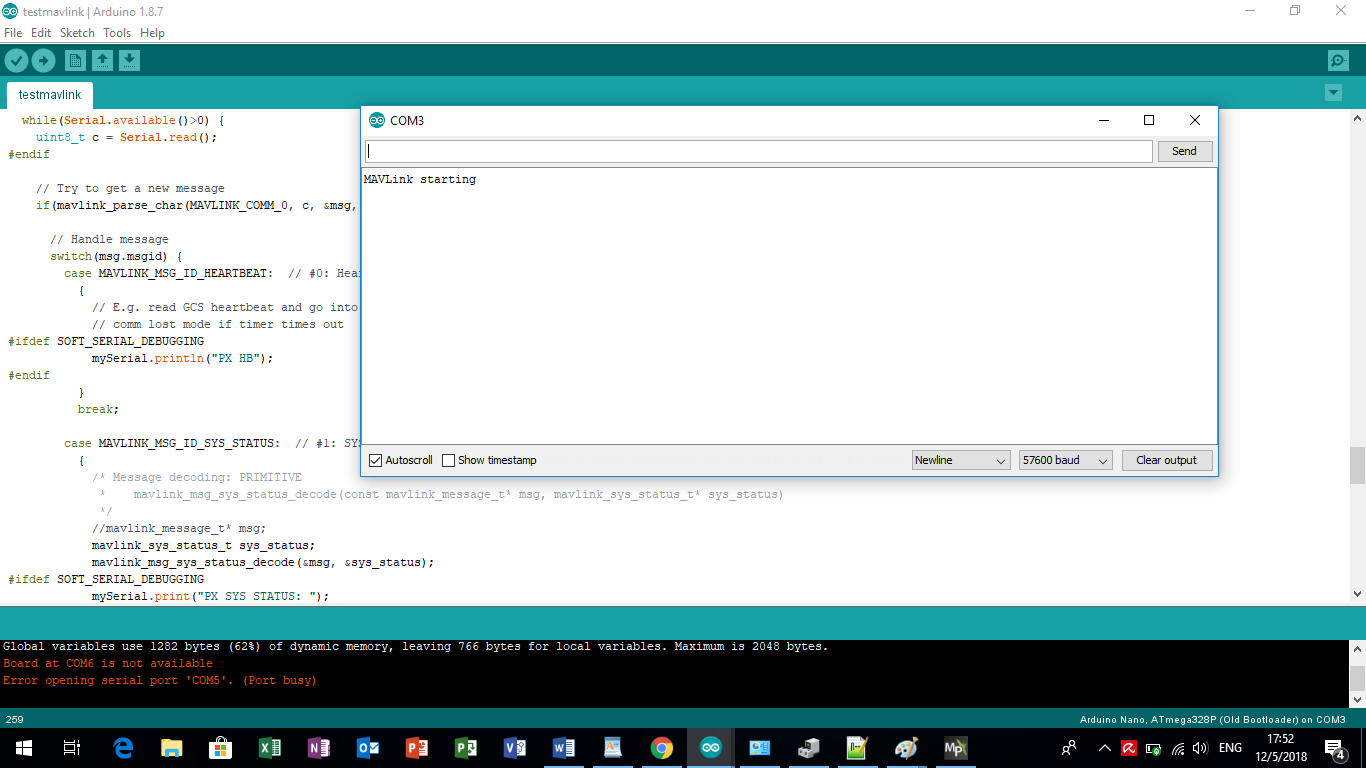
Hi @jplopezll:
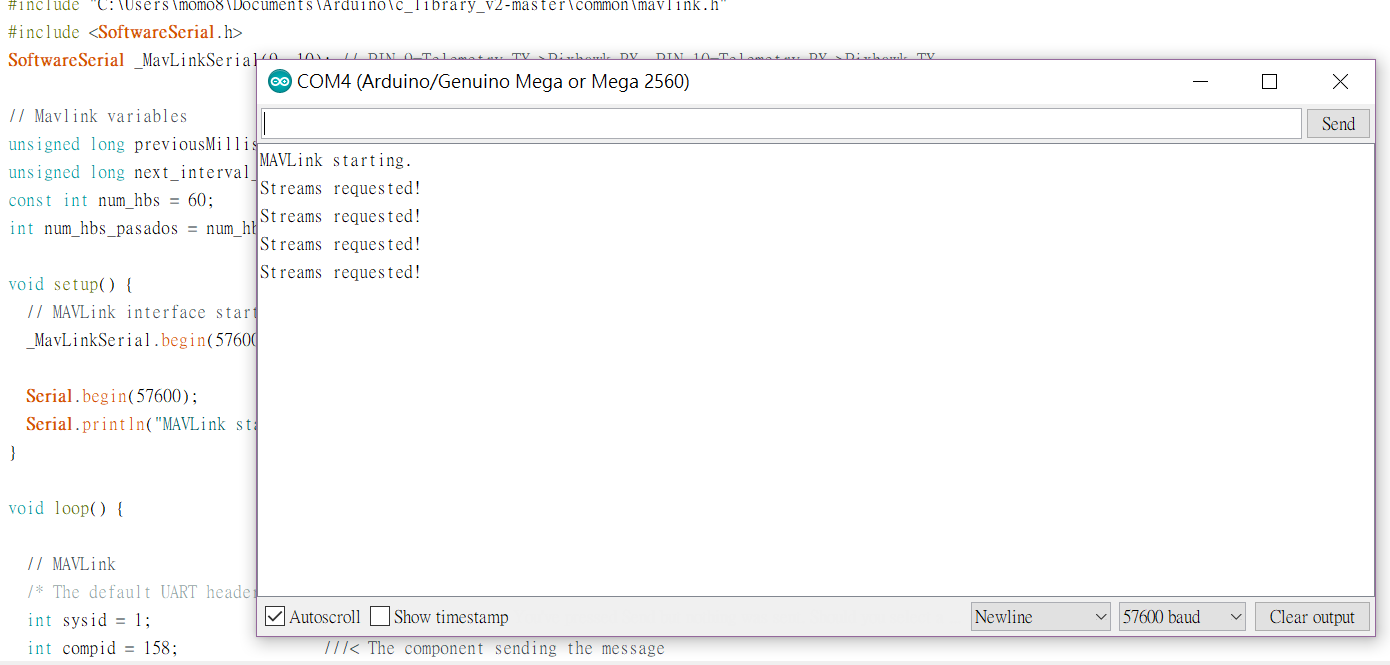
I have been tried to get heartbeat from pixhawk for some weeks now,
using the code that you post but i can see only the “mavlink staring” and “Streams requested!” on serial moniter.
Is something wrong with the hardware?? Thx a lot to give me some suggests =)
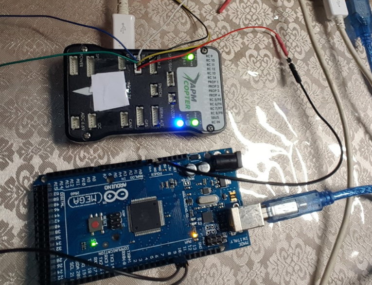
I cannot see very well the connections in the picture, in particular I cannot see the colors of the wires going to pins 9 and 10 of the Mega. They look like black and yellow, they should be the blue and green (see the drawing in the post).
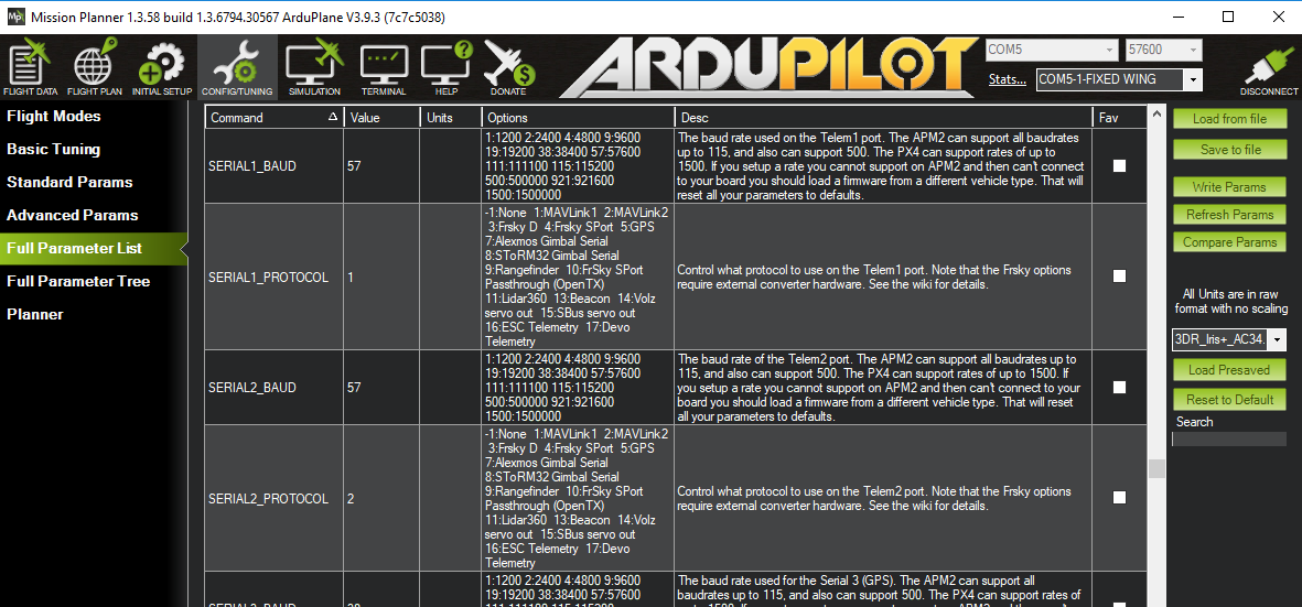
I assume that you have already activated the protocol on Telem1 using your preferred Ground Control. I do not know what sketch you are using with the Mega, please use the one in the post just above your message. It is more simple and easier to avoid errors.
@jplopezll :
I try to revert it.
But the result is the same. I have some questions. The blue one in telem 1 is TX and the green one in telem1 is RX? because i refer to the official pin assignments,
the blue is TX on pixhawk and the green is RX on pixhawk.
So it becomes to TX->TX RX->RX.
SORRY I’m a beginner asking you that question.
Not all pins on the Mega and Mega 2560 support change interrupts, so only the following can be used for RX: 10, 11, 12, 13, 14, 15, 50, 51, 52, 53, A8 (62), A9 (63), A10 (64), A11 (65), A12 (66), A13 (67), A14 (68), A15 (69).
This means you must chose a pin different than 9 for RX…