I am setting up a Quad using an Orange Cube and Kore Board and would like to use the Main Out pins 1 ~ 8 to control the landing gear and camera etc. using PWM but can’t get a signal out of the MAIN pins.
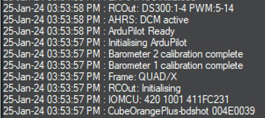
The motors are using AUX 2-5. RCOut: PWM:1-8 DS600:9-14.
To use the Kore board MAIN 1 pins to control the landing gear using RC channel 9 I have set these parameters.
SERVO_GPIO_MASK,255 (Servo 1 ~ Servo 8 set as GPIOs)
SERVO1_FUNCTION,59 (RCIN9)
The Mission Planner Servo Output window shows it is working and a Servo tester connected to the SBUS Pins shows Channel 1 is working but when I connect a servo or tester to MAIN 1 pins there is no signal.
Is this because the MAIN update rate is still at 400Hz instead of 50Hz??
They way I read it you can’t configure Bi-Directional DShot on the Cube MAIN outlet pins and you have to use the AUX pins, so I 'm short of servo outlets. Maybe I’m missing the big picture???
You said you wanted to use the Main Outputs for “landing gear and camera etc” with PWM. So, that’s not GPIO. You can use the Aux outputs for BDshot with current Stable or use the Main outputs with V4.5, a Dev version. So, not clear what you are trying to configure for.
Reset SERVO_GPIO_MASK to the default (probably 0), and then just set the SERVOx_FUNCTION to whatever you want.
Copter already has landing gear functionality (SERVOx_FUNCTION,29), so you may want to use that rather than RC passthrough. That way if you have the landing gear up it will come down on an RTL for example.
Thanks for the responses! Easly solved with the SERVOx_FUNCTION function as I just wanted to configure the MAINs PWM output but unfortunately I got distracted by GPIOs…
Concerning GPIO’s, the wiki seems a bit frugal in explaining what their actually purpose is, how they work and there are no examples
Can anyone help with this?
The hyperlinks in this statement from the GPIO Wiki are the best bet:
General Purpose Input/Outputs (GPIOs) are used in ArduPilot for control of relays, actuators, LEDs, camera triggers, Start Button etc. Some functions also use a GPIO pin as an input, like RPM Measurement.
The GPIO doc page is a bit messy because the structure of how they are configured completely changed a few versions ago making the page a bit busy.