Introducing Hybrid Project

New photo by Ryan Pope

Hello. We wanted to contribute to this blog by highlighting the development and flight testing of our Ardupilot controlled Hybrid VTOL platform, dubbed Hybrid Project for now. The first few posts will provide some background on our early development and prototypes. In the future I would like to submit weekly updates outlining the manufacturing of our airframe, along with flight testing data and developments.

Our primary goals have been to design and manufacture a gas-electric hybrid, long endurance (and BVLOS), VTOL platform in a way that keeps production costs minimal and proves that reliable, high performance sUAS’s can be had for a fraction of the cost of currently available aircraft.

Other design criteria include:

  • Modularity - the aircraft must be able to accept a wide variety of payloads without requiring complete re-design of the fuselage.

  • A mechanically simple starter for gas engine that doubles as a generator to charge the flight batteries and and other on-board systems as well as possible payloads.

  • The ability to operate in harsh conditions, including rain.

  • Aircraft needs to be simple to dismantle and re-assembled for easy transport.

Most of these criteria have already been integrated and flight tested with positive results. Some of the weather resistant and “easy take-down” features are currently in the design stage and soon to be manufactured.

We appreciate the vast knowledge contained in these pages. We hope that through sharing our experiences we can contribute, in our own way, to the Ardupilot community.

Stand by for more…

14 Likes

Looks great!
Is it an optical illusion, or does the A-tail really have no support between the two halves?

are you using the ICE module in ArduPilot to control that?
Can you give us some information on flight performance? (endurance, cruise speed etc)
Cheers, Tridge

1 Like

Thanks for stopping by!

There is no support between the tails, we feel our center section is adequately stiff in torsion to support the floating tail design. While there is some deflection on hard yaw, we prefer to keep it this way for now to simplify the breakdown/assembly.

We are using Modified (by us) Zenoah G26s for our pusher power plant. The starting/charging control is currently handled by ECU that we developed in house.

Basic Information:

Wingspan: 9ft
Takeoff weight: 35+ lbs
Typical cruise speed 25 m/s (90 kph, 56 mph)
Max Speed : 32 m/s (115 kph, 71 mph ) 18*6 prop - more testing soon - more pitch.
Flight endurance on full tank (1 us Gallon) greater than 5 hrs (this is tested - .bin FILE 1.5 GB )
VTOL voltage: 12s ~50V
Generator power output : Tested up to 500W, limited to 300-350W (otherwise not enough power to climb :slight_smile: )

ABOUT US:

Hybrid Project was born inside a machine shop in Tennessee a little over a year ago. We engineer and manufacture parts and complete assemblies for a diverse clientele, from local walk-in customers to large aerospace and silicon valley tech companies.

The Shop:
New photo by Ryan Pope

Shane Roberts, shop owner, is responsible for the majority of the design work, including developing, testing, and assembling the hybrid power-plant and management system (basically the complete fuselage).
New photo by Ryan Pope

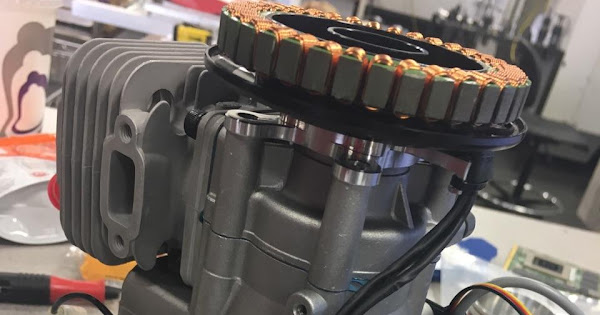
Hybrid system after wet weather testing (starting/charging in the rain):
New photo by Ryan Pope

Ryan Pope (that’s me!) contributes to the design (with a heavy influence on the flying surfaces), lays up composite, and fabricates/assembles/wires the various parts to make a complete aircraft, from my shop in Idaho. I also do the majority of the test flying.

After the very first, all electric, proof of concept flight (success):
New photo by Ryan Pope

Inner wing, upper skin layup:
New photo by Ryan Pope

Inner wing structure (more on this later):
New photo by Ryan Pope

Next entry I will give a quick history of how we arrived at our current design and what we plan to improve/accomplish this winter…

Thanks for looking.

5 Likes

very impressive!
I had a quick look at the log, and there were a few things that stand out.

  • the airspeed calibration is quite a long way off. Try comparing TECS.sp versus GPS.Spd while circling. TECS.sp averages 28m/s but GPS.Spd averages about 21. That probably means the ARSPD_RATIO is a long way off.
  • The DCM pitch estimate in AHR2.Pitch is quite a long way off from the EKF pitch estimate (I see discrepancies of 10 degrees at times). That may partly be from the airspeed estimate error, but could be sensor misalignment, or poor compass calibration
  • the compasses are a very long way off, so much that the EKF isn’t able to use them at all. There is also a lot of compass noise, but the main issue is the offsets. If it lost GPS lock then it would not be able to dead-reckon and you would almost certainly get a fly-away as it would have no idea what direction it was flying
    All of these things should be pretty easy to fix. Very impressive aircraft!
2 Likes

Thanks for looking over the log.

Yes, the compass offsets are terrible despite multiple attempts at calibration. Maybe I’ll take a video of how I do it to see if anyone can find and error in my method. More than likely the external compass needs to be re-located away from all the noise. I’ll be testing that soon.

Initially I struggled with the airspeed calibration, and the aircraft flew more consistent (less alttitude and throttle oscillation) with the airspeed disabled. But after utilizing the ARSPD_AUTOCAL it improved dramatically. I looked at a couple more recent logs and noticed the same discrepancy between TECS.sp and GS. When I was going through initial setup, I over-layed the GPS.spd on ARSP.Airspeed and the averages were similar. However, upon reviewing some recent logs, I have noticed that sometimes the difference between ARSP.Airspeed and TECS.sp is as large as 6 m/s. Any idea what might be causing this?

Hopefully, better compass and airspeed health will improve the pitch estimates. I will start there.

2 Likes

Wow, that thing is amazing!! Very nice work!!

1 Like

I ran dronekit-la over the log (22 minutes…). I seems to pick up a few things…

That’s probably baro drift.

   "maximum-altitude-absolute" : 1408.0999755859375,
   "maximum-altitude-absolute-units" : "metres",
   "maximum-altitude-relative" : 173.6099853515625,
   "maximum-altitude-relative-units" : "metres",
   "maximum-distance-from-origin" : 813.45686980047378,
   "maximum-distance-from-origin-units" : "metres",
   "maximum-velocity" : 38.107308907708244,
   "maximum-velocity-units" : "metres/second",
   "packet-count" : 35210537,
.
.
   "total-distance-travelled" : 417467.85829253669,
   "total-distance-travelled-units" : "metres",

All of your arming checks were disabled:

               "evidence" : [
                  "Arming flags: 0",
                  "NONE check disabled",
                  "ALL check disabled",
                  "BARO check disabled",
                  "COMPASS check disabled",
                  "GPS check disabled",
                  "INS check disabled",
                  "PARAMETERS check disabled",
                  "RC check disabled",
                  "VOLTAGE check disabled",
                  "BATTERY check disabled",
                  "AIRSPEED check disabled",
                  "LOGGING check disabled"

Positioning was somewhat of a problem - POS vs GPS is out a fair bit.

Sometimes the vehicle was having a few issues with its attitude control:

            {
               "duration" : 12.910907745361328,
               "duration-units" : "seconds",
               "evidence" : [
                  "threshold=10.000000",
                  "threshold-duration=0.250000 seconds",
                  "Max-Delta=30.400000 degrees",
                  "Roll-at-Max-Delta=2.500000 degrees",
                  "Desired-Roll-at-Max-Delta=0.720000 degrees",
                  "Pitch-at-Max-Delta=23.709999 degrees",
                  "Desired-Pitch-at-Max-Delta=-6.690000 degrees"
               ],
               "evilness" : 10,

and

It did pick up the discrepancies between AHRS and EKF.

It notes you have very large compass offsets. It also notes your compass vector lengths are getting quite significant:

               "duration" : 48.25421142578125,
               "duration-units" : "seconds",
               "evidence" : [
                  "threshold=600.000000",
                  "threshold-duration=0.250000 seconds",
                  "length-max=1073.054053"
               ],
               "evilness" : 10,
               "evilness-is-deprecated" : "Use severity-score",
               "reason" : "Compass Vector Length above threshold",
               "series" : [ "MAG.MagX", "MAG.MagY", "MAG.MagZ" ],
               "severity-score" : 10,
               "status" : "FAIL",
               "timestamp_start" : 1632012511,
               "timestamp_stop" : 1680266724

It notes EKF was very unhappy, and also specifically warns about terrain_alt_variance - a lot.

It notes you haven’t calibrated your current sensor (probably not a problem in your case!)

2 Likes

The ARSP.Airspeed reading is the apparent airspeed, whereas TECS.sp is the true airspeed. The true airspeed increases with height due to decreasing air density. At sea level the apparent and true airspeed values should be the same. Apparent airspeed is what keeps the plane flying (giving lift and control), but true airspeed is what is used for navigation (speed through the air mass)
The one you should compare to the GPS speed is true airspeed. If you are circling then the TECS.sp and GPS.Spd should have the same average at any height above sea level.
At the height you were flying (about 1300 meters) you should expect the ratio of true airspeed to apparent airspeed to be about 1.12. So at 24 m/s measured on the airspeed sensor, you expect a TECS.sp of about 27m/s.
A difference of 6m/s is quite a bit larger than expected, and probably comes from the EKF fusing in the IMU data. The poor airspeed calibration means the EKF is getting conflicting data, and its doing its best to sort it out.
Based on your 5hr log, it looks like you would need an ARSPD_RATIO of 1.2 in order to make GPS speed match the true airspeed from your airspeed sensor. That is a very low value, and indicates there may be a problem with your pitot or with the static port or with the tubing. Can you post some photos that should the pitot setup, including the tubing?
Note that if you do change your ARSPD_RATIO then your plane will start flying at quite a different speed, as all of the target airspeeds are apparent airspeeds. It will also have a (relatively small) affect on your tuning.
Cheers, Tridge

1 Like

It is also possible to calibrate a compass from a flight log. I just did that, and it gave very strange results. I suspect you may have the orientation of the compass incorrect? It seems to be off by 90 degrees.
I also suspect a high degree of interference from something else on the aircraft. What is generating EMI that is close to the compass?

ran dronekit-la over the log

Thanks for the feed back Peter.

Does that take into account that the aircraft spends more time in the upwind “leg” of the circle? It seems to me that the average ground speed (gps) would always be less in any wind, especially after a 5 hr flight (and 15 - 20 mph wind for much of that flight)

Bear with me if I am missing something obvious here.

Here is a picture of the wing avionics bay:
https://photos.app.goo.gl/JTtlTvEB5zSqC4U52

The pitot tube is temporarily mounted and exposed to clean airflow here. The static ports may be getting close to some boundary layer interference?

The ring terminals toward the front are attached to the power distribution bus bars for the quad ESCs, a likely source of noise and interference for the compass, but hopefully not when in fixed wing mode. I plan on moving it out of the bay for testing this week.

Updated my second post with a quick background of the project.

you are correct, I misused the term “average”. Normally you eyeball it on the graph and look for symmetry of the GPS speed deviation from the airspeed. The airspeed should be constant, and GPS speed deviates by the same amount either side. A strict time average will indeed be off as it spends more time upwind than downwind.
The airspeed autocal code does take that into account properly, but I’d suggest you not use that at the moment while you are sorting out the pitot install.

are you sure that is clean airflow? I could imagine the nose of the fuselage interfering with that in cruise speeds. The static port also looks suspect as you suggest.
I suggest you fly with airspeed logged and not used (set ARSPD_USE=0) until you get good consistent results. The best spots for the pitot looks to be up on the nose, mounted on a bracket that takes it well above the fuselage (there are some nice 3d print designs available).
Cheers, Tridge

Hi Tridge, can you please tell us how to you calibrate compass using logs. I looked up the documentation and I cannot find it. Is there some app/script you use to do so? I have seen the COMPASS.LEARN in fixed wing to be pretty useful. When we set this pretty soon the logs show that MAG1/2/3.X match and so do Y, Z axis. Unfortunately this flag seems to have no effect on Heli/Multis.

there are several different method. One is to use one of the magfit scripts in pymavlink, like this one:

there are actually several tools for different situations.
My favourite at the moment is a new graph I’ve added in MAVExplorer which plots the world magnetic model predicted magnetic fields against the measured fields for a flight. That allows you to really see easily what is wrong. Unfortunately that isn’t available in the widely used tools like MissionPlanner yet. I hope to include it in a future update of MAVExplorer for windows.

Testing!
New photo by Ryan Pope

Goals of the day:

  1. Test pilot/static tube mounted in nose.

  2. Relocate GPS/Magnometer farther away from noise and re-calibrate, test fly:

  3. Test a steeper pitch prop (18x8 vs 18x6)

  4. Don’t freeze. (38deg F and always windy!)

DOWNLOAD: Flight log with after airspeed and GPS/MAG relocation

Pitot tube was re-located to the forward most point on the AC to rule out any adverse airflow interference. The sensor was mounted about 5" directly behind inside the nose. Lengthened harness with shielded wire due to its proximity to HV battery leads.
New photo by Ryan Pope

GPS/MAG was relocated as shown:
New photo by Ryan Pope

Existing external compass was disabled (unplugged)

I did the live calibration “dance” and it returned improved (in the green) offsets compared to before.

I left airspeed enabled for the first flight assuming that given the deviation in the previous log the aircraft would mostly attempt to transition and fly at a higher airpeed. It seems from a few log samples that there indeed was an issue with the previous temporary location. The aircraft did visibly and audibly transition and fly faster across the board in auto mode (cruise set to 25 m/s). I adjusted FBWmin and Cruise down accordingly.

New photo by Ryan Pope

Compass health was still a major issue as usual. As soon I arm and begin to climb (Q_Stabilize) I get a slew of messages, ultimately ending with a constant “Bad Compass Health” message and obvious real indications in hover of the aircraft searching for heading, as well as confusion in FWD flight according to the heading bar via telemtry.

Executing nav command ID #17
EKF2 IMU0 switching to compass 1
EKF2 IMU1 switching to compass 1
Transition airspeed reached 19.2
EKF yaw reset -54.41
Reset alt target to 16933.1
EKF2 IMU0 switching to compass 1
EKF yaw reset 60.20
EKF2 IMU1 is using GPS
EKF2 IMU0 is using GPS
u-blox 1 HW: 00080000 SW: EXT CORE 3.01 (107900)
EKF2 IMU1 Origin set to GPS
EKF2 IMU0 Origin set to GPS
EKF2 IMU1 tilt alignment complete
EKF2 IMU0 tilt alignment complete
Init HOME
EKF2 IMU1 initial yaw alignment complete
EKF yaw reset 28.96
EKF2 IMU0 initial yaw alignment complete
GPS 1: detected as u-blox at 115200 baud
Ground start complete

It does seem to follow its course or paint very nice circles in loiter mode despite this, even in high wind (filters hard at work, no doubt).

Any ideas concerning the Magometer error? Would it help to disable the internal compass? I was hoping to test this. Mag2 (internal?) is a mess during Q take off, and seems like some dependencies are set during that time that may negatively affect fixed-wing flight?

For those of you interested, the 18x8 was definitely too steep for our setup and even off charging would not allow enough RPM for an increase in top speed. It did however allow us to cruise at a lower RPM that we have found to give us excellent endurance on the static test stand, albeit at the cost of thrust needed for good climb performance at MGW. Wouldn’t we all love a variable pitch prop (and controller) :slight_smile: !

That’s is for now! Thanks for the interest and suggestions. We will regularly keep moving forward with design and testing.

New photo by Ryan Pope

Some more pictures for your viewing pleasure:

Hybrid Protype:
New photo by Ryan Pope

New photo by Ryan Pope New photo by Ryan Pope New photo by Ryan Pope
1 Like

Nice work! I’d suggest a flight with the internal mag enabled, but not used, would give a good data point. This way the mag values are logged but not fused.

1 Like

nice work! I’ll have a look at the log soon
btw, here is a more rapid takeoff of a quadplane:

Man that is impressive. What kind of airplane is that? Maybe I should scrap the FF6!

its our cheap test plane for new quadplane code, a Firstar from hobbyking
We will happily swap it for yours :slight_smile:

1 Like