With wp_radius = 0.1 I set the ATC_STR_ANG_P parameter between 1 and 5 (2.5 is default) and found no improvement.
The reason that the WP_RADIUS parameter is so critical is because Rover doesn’t plan the corners well. What I mean by this is that the navigation controllers only know about the waypoint they are currently going towards. They don’t consider the next waypoint after the current waypoint.
The sequence of events is, once the vehicle enters the WP_RADIUS, the navigation controllers are stopped and the vehicle straightens the steering and slows to a stop, it then turns towards the next waypoint and then finally re-starts the navigation controller to move towards the next waypoint.
If the WP_RADIUS and ATC_ACCEL (or ATC_DECEL) are perfectly matched then the vehicle will stop very close to the line between this waypoint and the next one but if they’re not then the vehicle will either stop too early or drive too far past the line. This leads to a lateral position error that the navigation will try to get rid of by turning towards the line.
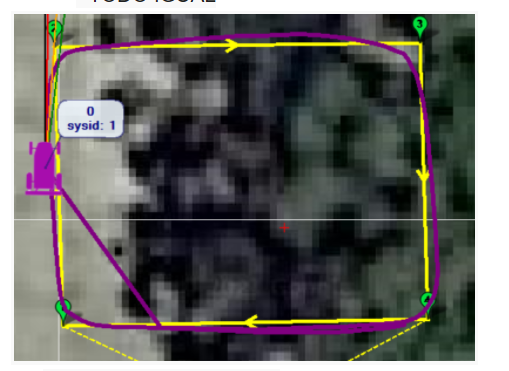
In some of the pictures shown above we can see the WP_RADIUS is too small (compared to the ATC_ACCEL/DECEL) so the vehicle overshoots the line and then turns back.
When set perfectly the vehicle comes to a stop close to the line and the result is a decent square.
This issue is why we want to introduce SCurves to Rover.
1 Like
Thanks Randy for helping with that good explanation, which helped me also.
@comodin, you might try decreasing the deceleration (either with ATC_DECEL or with ATC_ACCEL - see Tuning Speed and Throttle — Rover documentation (ardupilot.org)) to a very low rate (just for testing right now) and set WP_RADIUS very small and see if you achieve a very close approach to your WP, to build confidence that you can hit the WP on the nose. Then you can increase the ATC_DECEL to an acceptable rate for your purposes and adjust WP_RADIUS up some to compensate for the higher speed at which the vehicle will approach the WP. Eventually, you will get the deceleration and the WP radius matched.
1 Like
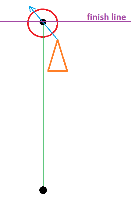
A final note from me re WP_RADIUS, the vehicle doesn’t give up on the current waypoint until it enters the WP_RADIUS or crosses the “finish line” so if WP_RADIUS is set too small the vehicle will try to turn towards the waypoint right up until it is very close to it which leads to overly aggressive turns right at the end of each segment… and those turns are pretty random because they depend upon which side of the green line the vehicle is on and how much lateral position error there is.
1 Like
Good point. I probably should have quantified my “very small”. @comodin, with the deceleration turned down so the rover slows way down as it approaches a waypoint, perhaps set WP_RADIUS to 0.5 and see what happens. If it stops short, change it to 0.4, etc. (And Randy, please override anything I say that you feel is not right for 2 reasons (1) you have way more experience than I, and (2) on top of that, this is a small rover, unlike anything I have ever had.  )
)
1 Like
Hi ,
I was configuring the ATC_ACCEL (or ATC_DECEL) parameters and found no improvement so I was searching deeply in this forum looking for an answer and I found in this topic how @rmackay9 was analyzing certain graphs.
I must say that I am a novice in this type of analysis but it caught my attention that my graph on speed and steering were so different from what @rmackay9 pointed out.
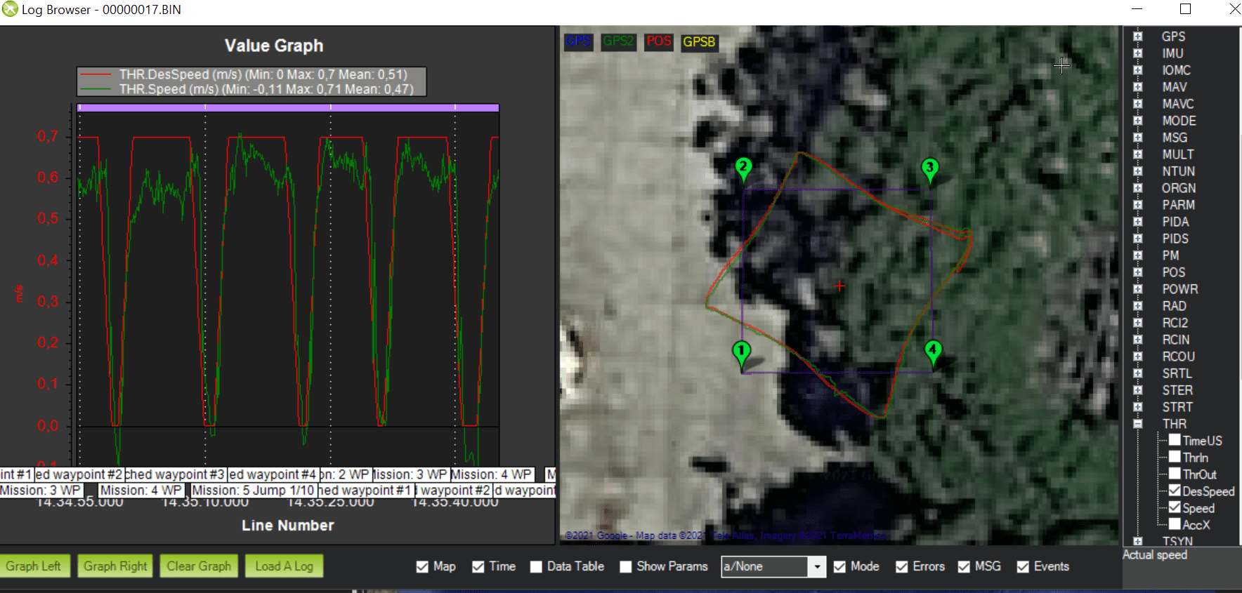
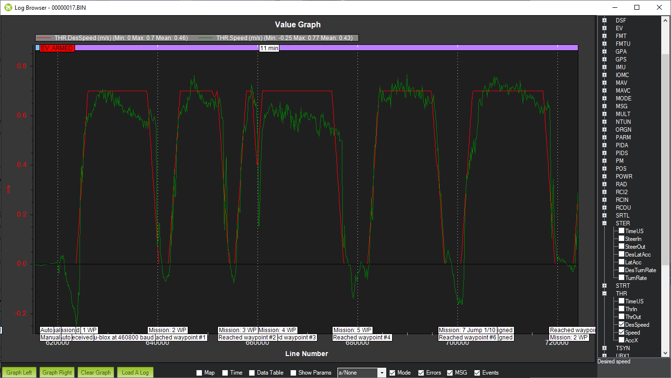
SPEED with wp_radius = 0.1

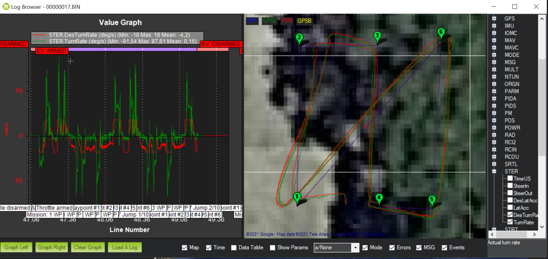
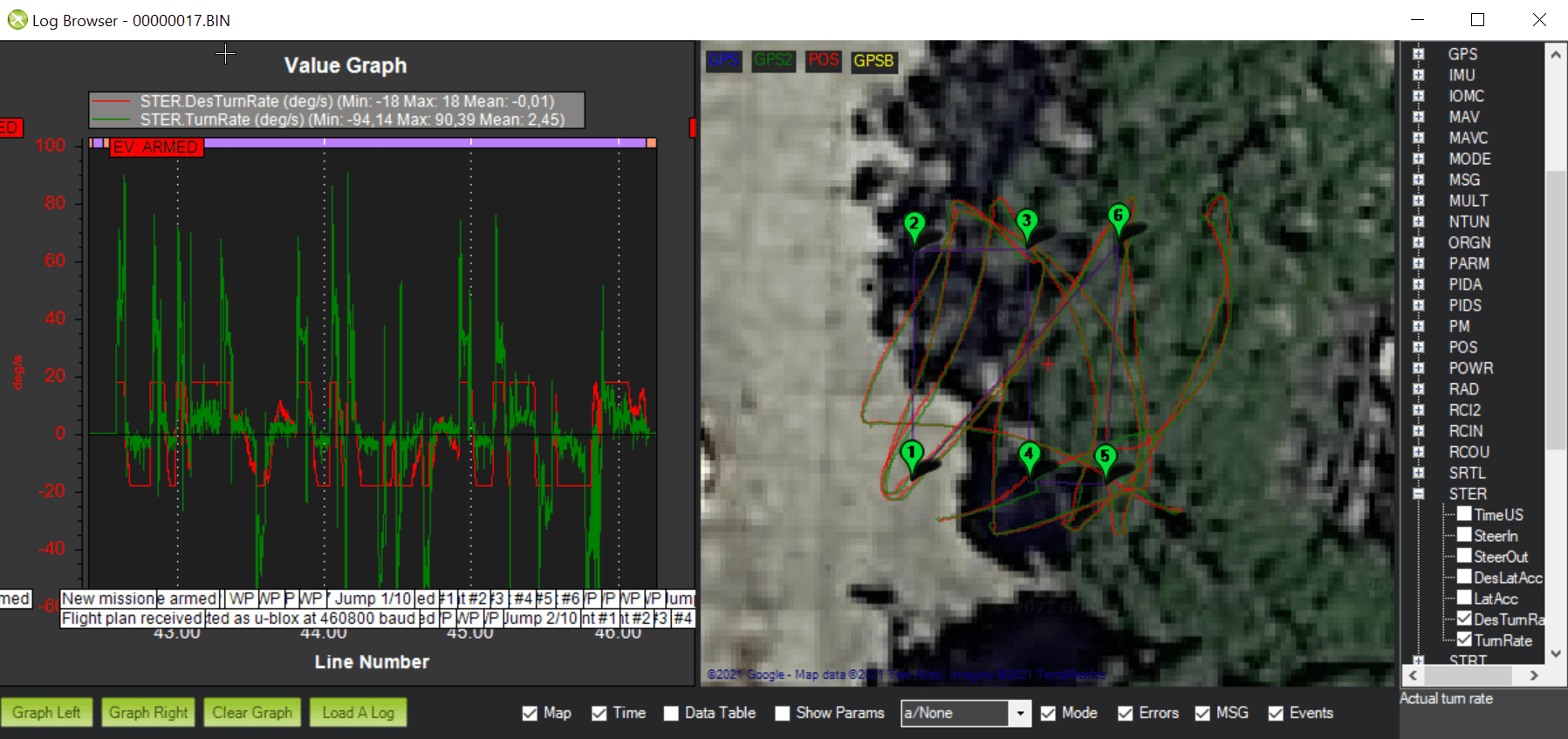
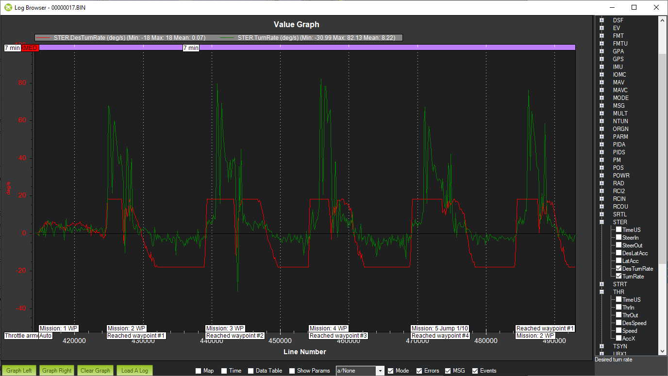
STEERING with WP_RADIUS = 0.1
So I started all the tuning from scratch again.
https://ardupilot.org/rover/docs/rover-tuning-process.html
I think I have improved the SPEED theme quite a bit and it is now more coherent.
And as @ktrussell rightly says, every time you read the wiki you find something new.
In this case I’m talking about ACRO_TURN_RATE
Following the instructions I find the following graph (it was always turning to one side and to the other, but as it is a skid vehicle it was always turning on its own axis)

And as the wiki states
“Note the value shown may be in centi-degrees/sec so its value should be divided by 100 to match the parameter’s deg/sec”
If the maximum values were -2000 and 2000 I divided them by 100 and therefore 20 so I set it a little lower, i.e. to 18. I probably misunderstood?
As a result, the ACRO_TURN_RATE parameter is changed from 180 to 18 =180 to ACRO_TURN_RATE =18.
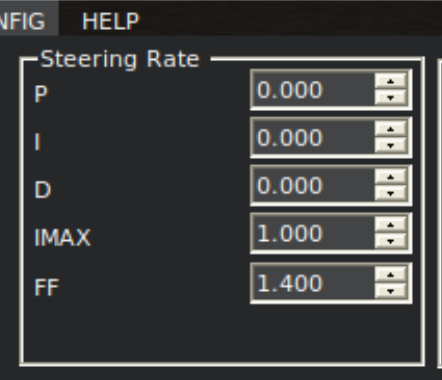
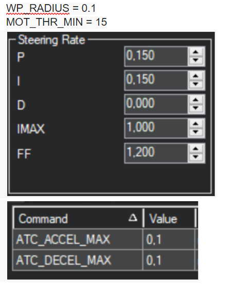
I then continued with the PID of the steering rate and went from these initial parameters
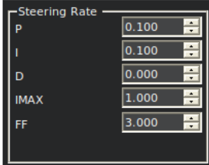
to these final
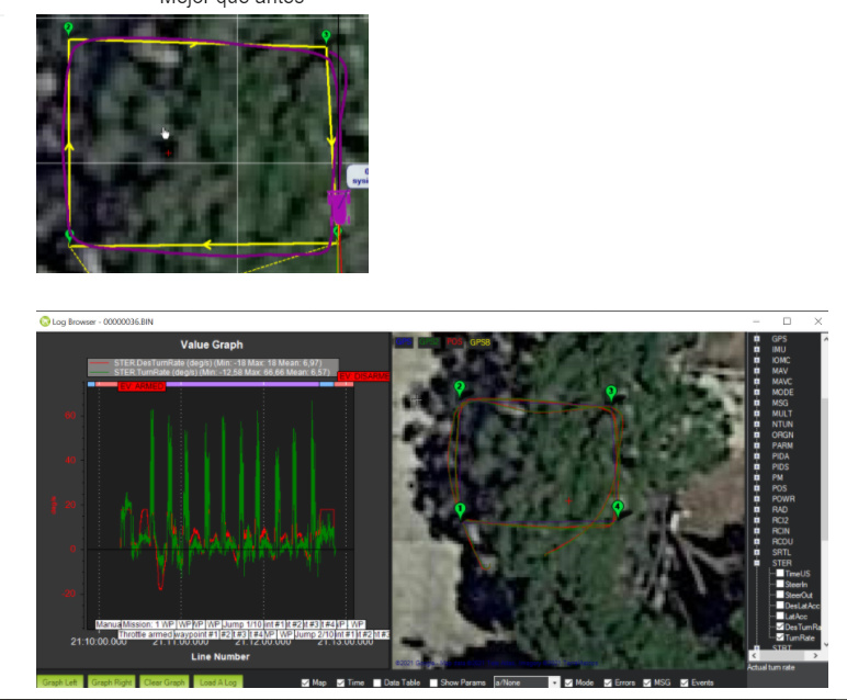
Before continuing with the wiki I tested the mission again with WP_RADIUS = 0.1 and I found an improvement. Now the track between waypoints was more correct.
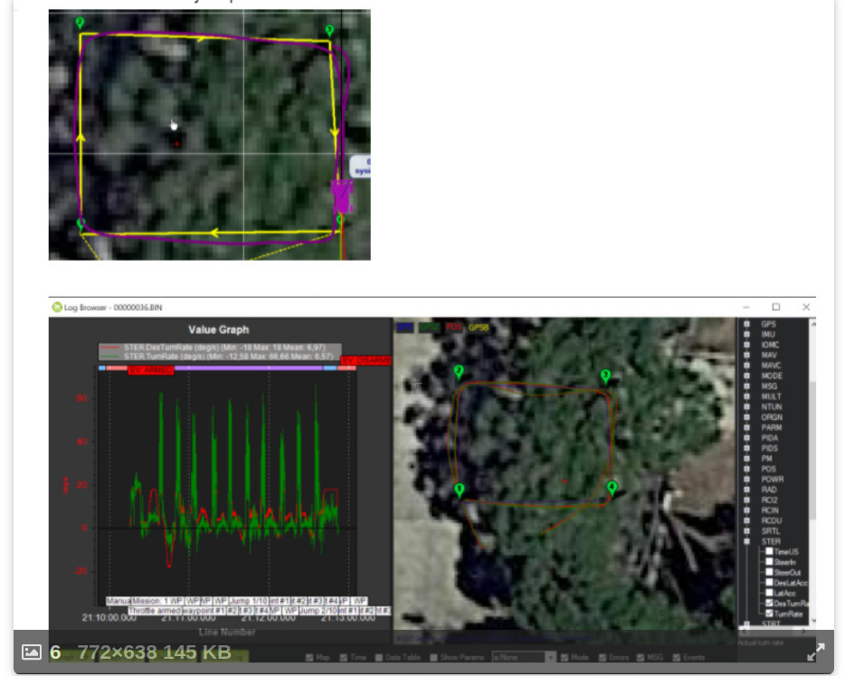
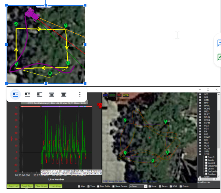
However I analyzed the steering graph and it seems a bit strange, doesn’t it?

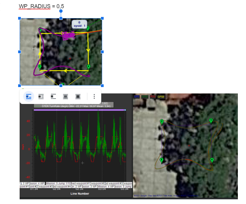
As I indicated at the beginning this prototype is only the proof of concept for a bigger one that will be dedicated to agriculture where the “streets” between crops will be 80cm so the turns must be exact, that’s why my insistence on WP_RADIUS = 0.1.
For example I put a “similar” mission and the results of new ones were very diverse and some very frustrating.
WP_RADIUS = 1
WP_RADIUS = 0.1
I am sending you the log of these graphs if you would be so kind as to analyze it.
It is a single log where I have been changing the WP_RADIUS parameter.
BIN : https://drive.google.com/file/d/1vcSGRgXGRL769ePd5sUkWKz5AOExKsfd/view?usp=sharing
TLOG: https://drive.google.com/file/d/1dMWs850Bq4JwJOJ_s-xhMA1b8j8BaAYX/view?usp=sharing
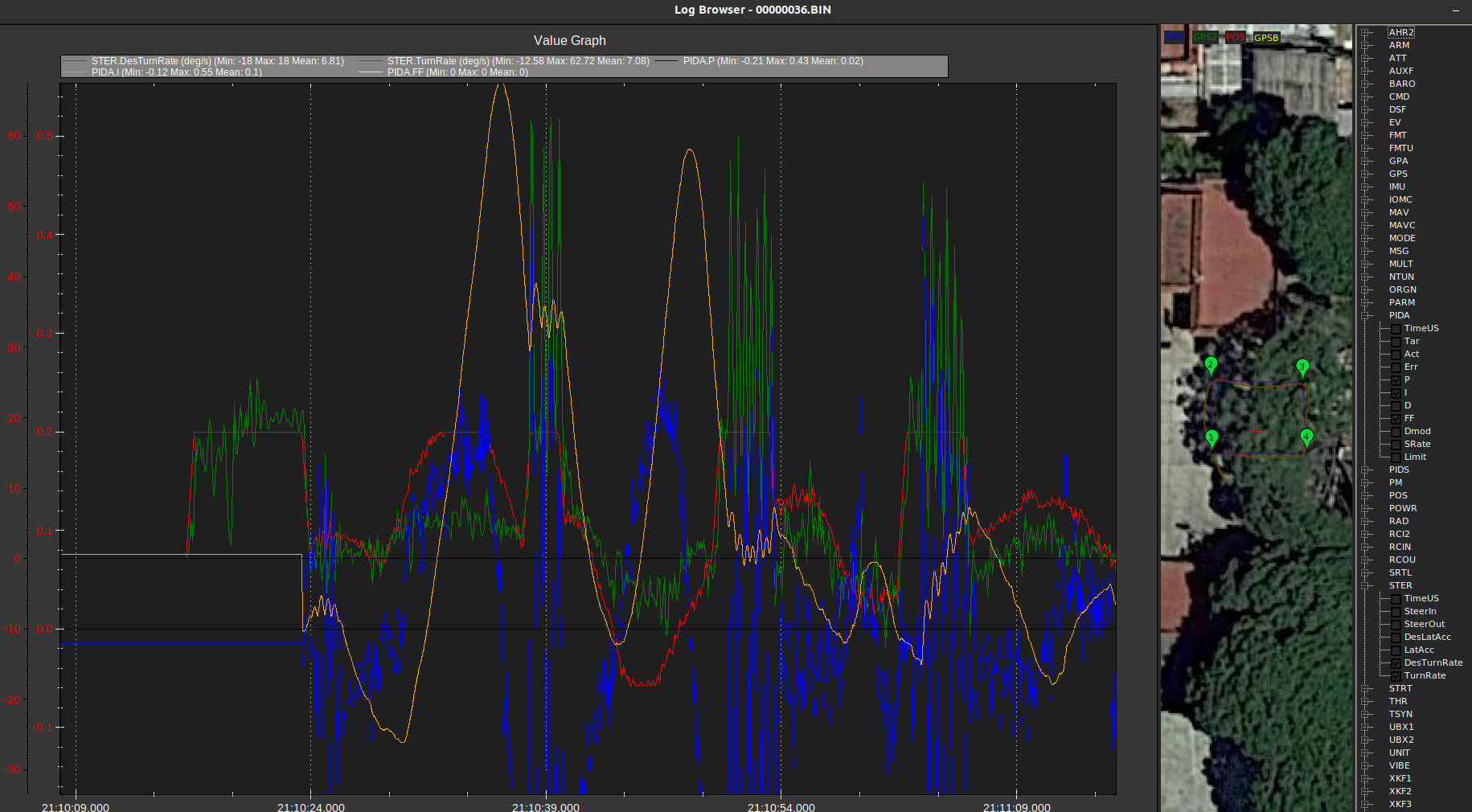
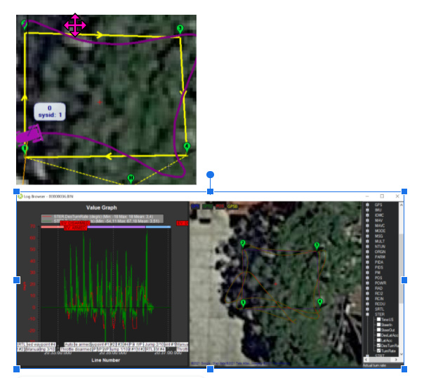
I had a quick look at the logs and the speed tuning is pretty good with the desired and actual sticking pretty close together.
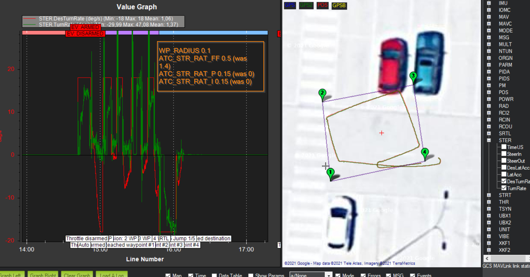
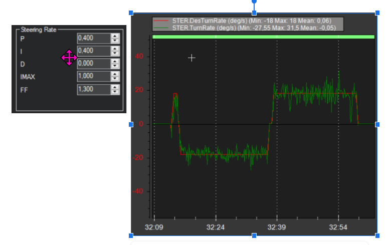
The turn rate tuning is showing a lot of overshoot though.
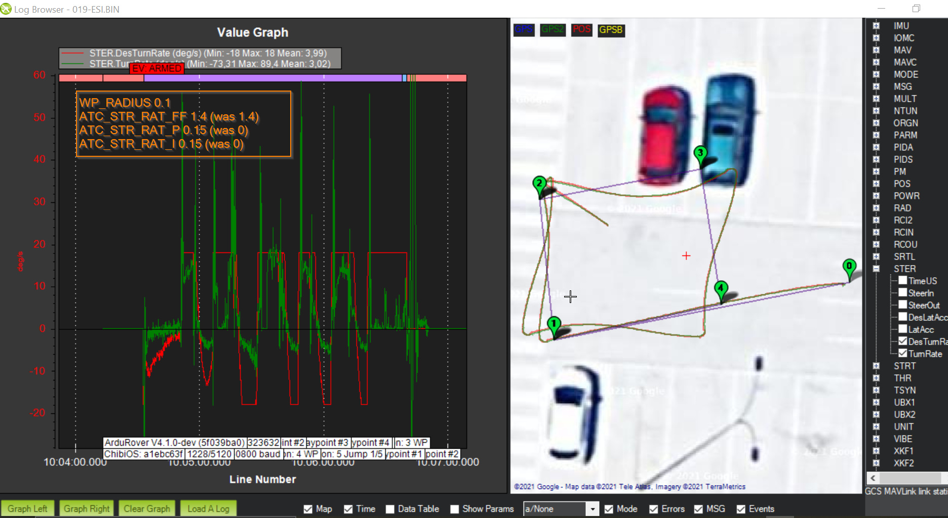
From the PID graph it looks like the response is all from FF so I’d make these changes:
- ATC_STR_RAT_FF 0.5 (was 1.4)
- ATC_STR_RAT_P 0.15 (was 0)
- ATC_STR_RAT_I 0.15 (was 0)
As Kenny suggested higher up in the discussion if tuning in Auto it would be good to test with longer straight paths. The reason is that the corners add a ton of disturbance so it makes it less clear if the speed and turn rate controllers are working well or not. Normally I recommend tuning the turn rate controller in Acro mode instead of Auto but I suppose using Auto keeps your hands free… the problem with using Auto though is that you’re only going to be seeing pivot turns so it is a very specific repetitive situation. I think using Acro will allow you to test out different turn rates and see the response and get closer to the ideal tune.
… anyway, maybe the param settings above will work a bit better…
1 Like
Hi all,
I have gone to another site where there is more space to see if I can find differences by having the waypoints more separated.
@rmackay9, about the parameters you recommended.
It turns out that any value less than 1 in ATC_STR_RAT_FF causes the vehicle to barely respond to turns or very very slowly. Check out the video. (with this parameter = 1)
I usually do the setup in ACRO but later do a batch of missions in AUTO so that later I can properly compare the graphs obtained.
In ACRO and with ATC_STR_RAT_FF between 0.5 and 1 the vehicle barely responds to turns.
If in acro ATC_STR_RAT_FF <1 the vehicle barely wants to turn on its axis.
I understand that in the graphs, as you indicate, there is a lot of overshoot, but “visually” the vehicle needs almost an ATC_STR_RAT_FF >2.
@ktrussell , indeed with lower values of ATC_ACCEL (or ATC_DECEL) the vehicle seems not to “overshoot” the waypoints. They were at 0.4 and now I’ve set them to 0.1
I show you some graphs with the values of the parameters to see if you can advise me on the next step:
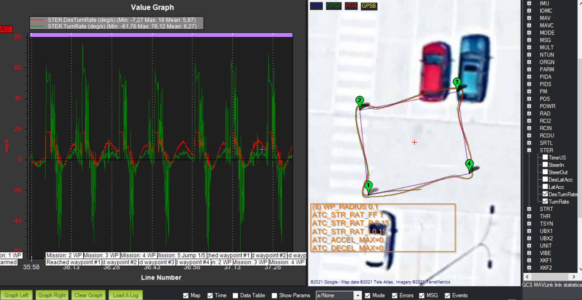
Thanks
Maybe the steering response is very non-linear.
I see that MOT_THR_MIN has been set to 20% which is the parameter’s maximum recommended value. I guess you followed the instructions on setting Minimum Throttle? I suspect maybe you still couldn’t get the motors to spin at a low throttle percentage and this led you to set it to its maximum of 20. FYI, parameters can be set to values higher or lower than the recommended values from MP’s full parameter list or full parameter tree screens.
1 Like
For skid steering vehicles where pivot turns are important, I think you need to be careful with MOT_THR_MIN. Too high a value will almost certainly prohibit good pivot turns.
I’m wondering if some ATC_STR_RAT_MAX or ATC_STR_ACC_MAX clamping might be of value here? The desired rate jumps quickly followed by a somewhat slow ramp of achieved rate until the achieved rate accelerates and overshoots. Might that be improved by limiting the rate or acceleration in those parameters?
2 Likes
This advice from Yuri sounds good to me too.
2 Likes
Hi,
Sorry for my late reply. I had my week holiday.
About MOT_THR_MIN … yes, I followed the instructions on setting Minimum Throttle but I got 20 value to spin all the motors.
I repeted again this and I can get 18.
One question, should spin all the motors or just one of each left and right side?
Anyway, then I thought maybe I had to calibrate ESC but I can not do it.
From Mission Planner I got this error.
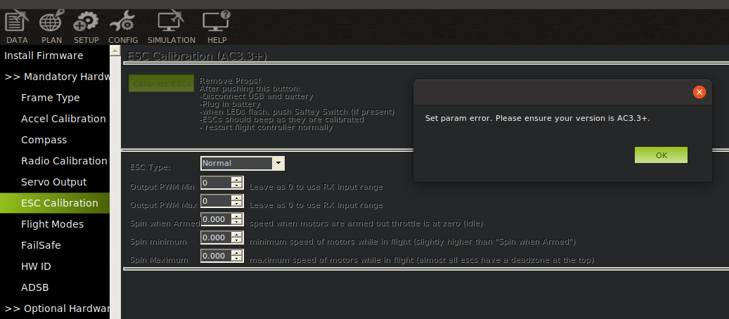
(I remenmer did that with my copters and working well)
So, I tried manually like this https://ardupilot.org/copter/docs/esc-calibration.html and as well not working well.
I have brushed motor 100 rpm (vcc) with this ESC
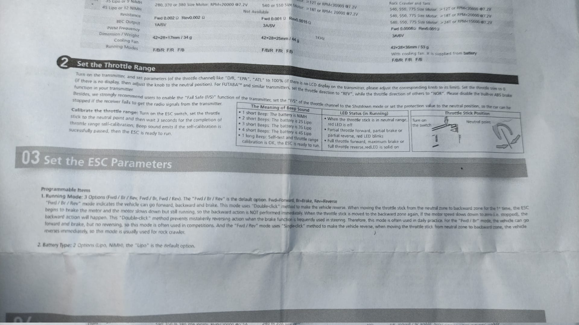
But I think is already well calibrate.
Tomorow I’ll try with ATC_STR_RAT_MAX or ATC_STR_ACC_MAX parameters than @Yuri_Rage sugguest.
I think MOT_THR_MIN should be set to the highest value possible where no motor movement is evident.
For testing purposes, you could try setting it to 0 and compare results.
You can follow the instructions for the ESC to calibrate it without using Mission Planner at all. As long as it powers up in calibration mode (usually by powering the Rover up with the transmitter throttle set to high), you should be able to get it done.
Then maybe I could lower the value a bit more, maybe to 16.
I’ll do.
I have tried several times manually but I can’t see any difference, so maybe I’m not doing it correctly.
I will try again.
I don’t think that most brushed motor ESCs can be calibrated.
Hi,
I started with what @Yuri_Rage proposed.
My starting parameters were as follows;
With WP_RADIUS = 1
 ![3|690x331]
(upload://spT4SFZzGcQ2Vq1CYwr3pVigYo1.png)
Everything starts to get worse when I decrease the WP_RADIUS parameter to < 1
-
MOT_THR_MIN = 0
WP_RADIUS = 0.5
Now with
-
MOT_THR_MIN = 40
WP_RADIUS = 0.5
So I consider MOT_THR_MIN = 15 to be the best I have.
Now with this parameters with this start:
- ATC_STR_RAT_MAX=18
- ATC_STR_ACC_MAX = 180
After test the best should be
- WP_RADIUS = 1
- MOT_THR_MIN = 15
- ATC_STR_RAT_MAX=18
- ATC_STR_ACC_MAX = 36
As I have not found a huge improvement I have tried again to improve the PIVOT_TURN.
I set it to ACRO and by simply rotating it on its same axis I try to adjust FF and P and I.
I think that at least in the graph it seems to be more in line with these parameters
But even this way if the parameter WP_RADIUS <1 I don’t get any improvement.
Sincerely I begin to think that maybe the misadjustment is somewhere else because although I understand that the tuning process is tedious I never thought it would take so long to obtain a positive result.
Are you sure that I should continue in this line or do you think that maybe the gps+heading is the one that is not working well?
Thank you for your support and I certainly need some light so I don’t start to get desperate.
2 Likes
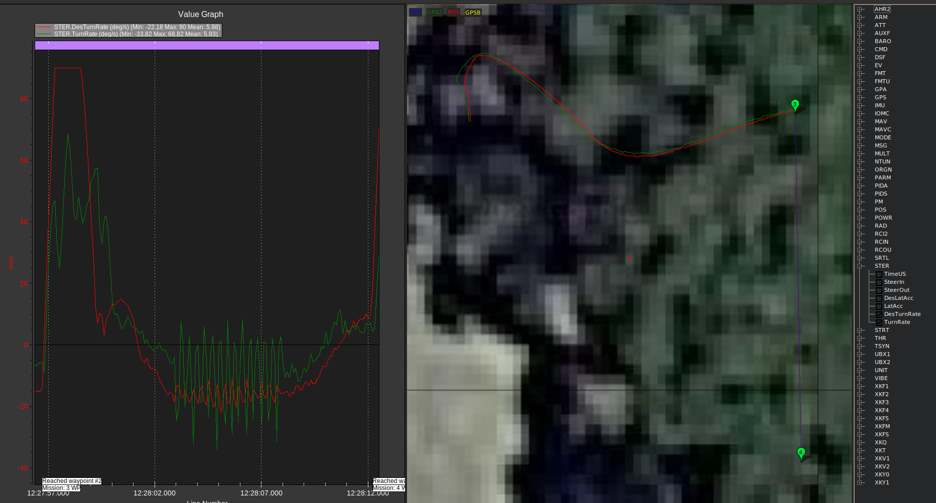
I think you should stick with the config that gives the best results above (e.g. WP_RADIUS = 1, MOT_THR_MIN=15).
The turn rate control looks pretty good in the picture above although we’re only seeing one turn rate (20deg/sec) and we can’t see the FF, P and I components of the output.
I think it would be good to test with some long segments (at least 10m, hopefully even longer) to see how good the navigation control is.
I think SCurves is coming in the not too distant future. It might still take a month… but surely not as much as two months.
2 Likes
@comodin, I don’t have much to add to what Randy is suggesting, but I am curious if you tried 0.9, 0.8, etc. for the WP_RADIUS, since 1.0 was pretty good, but a little short of the WP, and 0.5 went long (and a little crazy).
1 Like