Argh
Its a bad cable. I change the cable and get Pixmode…accurate measurements grrrrr.
thanks Patrick for your help. As always its appreciated.
Argh
Its a bad cable. I change the cable and get Pixmode…accurate measurements grrrrr.
thanks Patrick for your help. As always its appreciated.
Damn I still get bad Lidar health on mission planner. Grrrr.
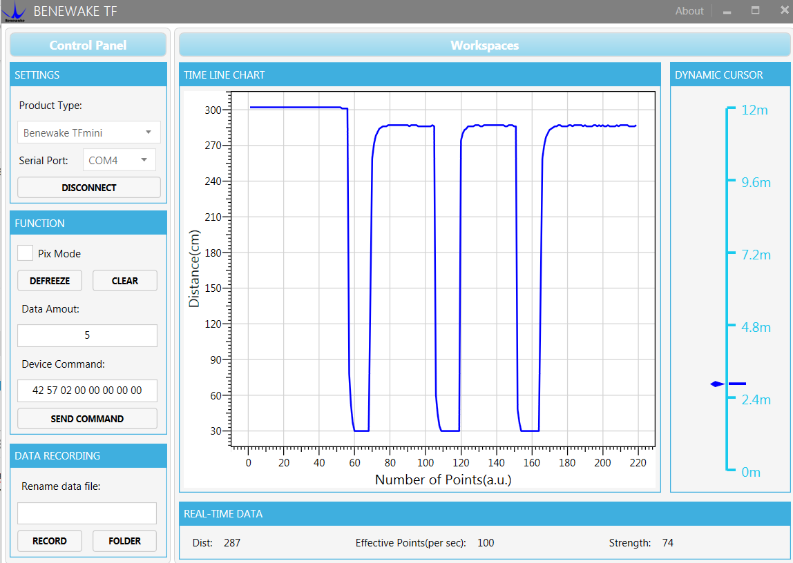
In TF Gui its spot on in Pix Mode…
Can you read it if you connect to a terminal @115200 (you can use Arduino Serial Monitor)
I have not tried.
I used the TF GUI and I can see its in PX Mode and MM. What would Arduino Serial Monitor show me.
um is the flight controller powerful enough to power the TF Mini…hmmm
PixHawk ok
PixRacer No
Recommand using UBEC
Working.
First the cable.
Then the right config…Pix Mode. Finally
Lastly the port was wrong. Pixracer documentation is a little thin on serial ports.
Works ever so good
I am using a pixhawk mini, px4flow, tfmini, and arduino pro mini as well as an I2C splitter for a position control system on my drone. The arduino and tfmini are both powered by UBEC. I have isolated the problem to the arduino board (tfmini parameters are correct and runs on Benewake in standard mode, also px4flow logs are fine). Despite uploading the given INO to the board… In MP the sonarvoltage and sonardistance both show “0” as well as a voltmeter reading of “~0V” at the AD4 and AD5 pinouts on the arduino. I have run other sketches on the arduino and have proven that it is in fact functional. Any tips on where to go from here would be greatly appreciated!
Hello Grant, First , just to make sure;
You have the TFMINI RX-TX connected to Arduino TXD-RXD ?
And the I2C SDA (A4) is connected to Flight Controler SDA an the SCL(A5) to FC SCL ?
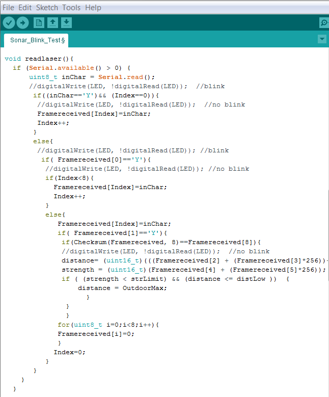
Please note that I added a new sketch on gitter its called:
BeneWake_TFMINI_I2C_ProMini_Maxbotic_Fast_Blink.ino
Basically it toggle the LED (13) on evry successful TFMINI readings, it is quite fast blinking, so its shows solid red but in the case there is no reading at startup it stays off.
Thanks for the reply! I have double and triple checked the connections on the Arduino and FC… I also ran Fast_Blink.ino, which resulted the red light staying off. But, the code on gitter did not compile so I changed the last few lines from this:
void loop() {
readlaser();
for (int i=0; i<100; i++){
}
to this:
void loop() {
readlaser();
for (int i=0; i<100; i++){
}
}
before running.
Considering this alteration did not change the output of the code, what does this tell you about where my problem is?
Oups… sorry, this timing loop was not meant to be there… I just removed it
But once this removed, does it get red ?
Thanks. Removed the loop and still no red
Then it looks like TFMINI is not set to proper mode
Then it looks like TFMINI is not set to proper mode
I have connected my TFMINI to benewake tf, received output that made since, and sent “42 57 02 00 00 00 01 06”.
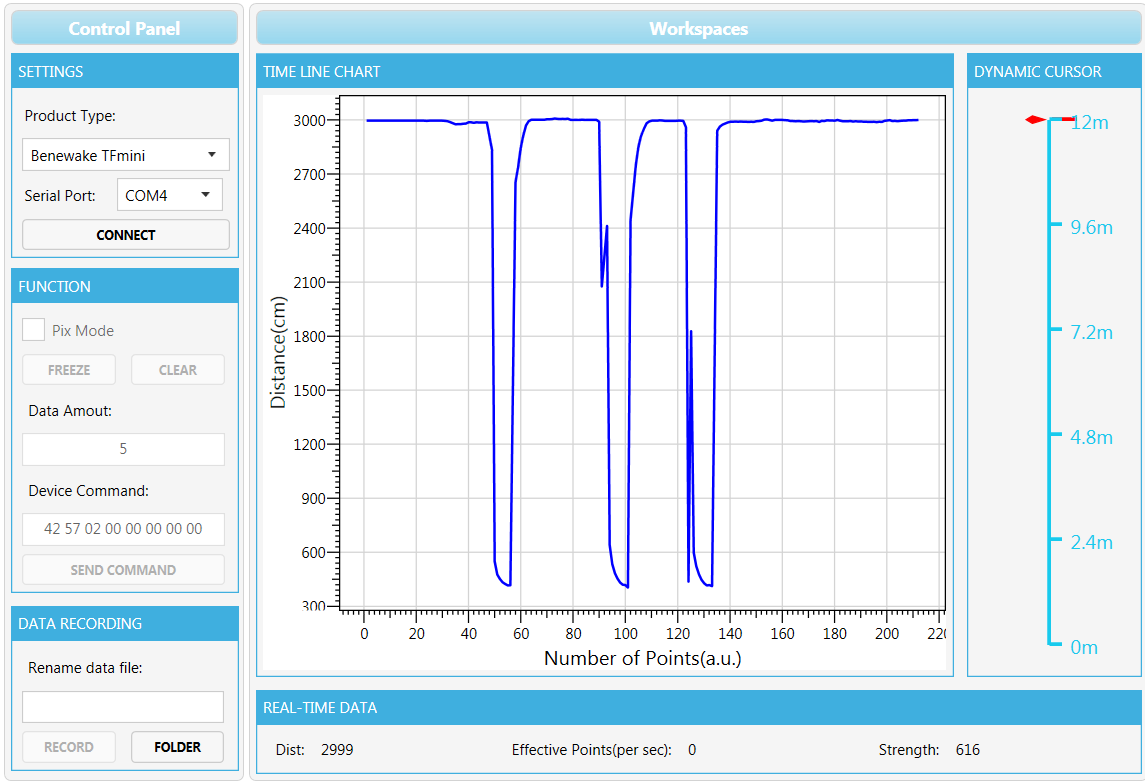
This is how the benewake window looks after a reboot…
I have also ran a test in which I hard coded a non variable distance measurement into the Arduino sketch. I was able to read my entered value in qgroundcontrol’s analyze widget. The problem is cornered to the output of the TFMINI, but it is almost as if the mode change will not stick. Thanks for your help.
Ok I see you send in cm , try switching to mm
Modify output unit to mm output: 42 57 02 00 00 00 00 1A
Modify output unit to cm output: 42 57 02 00 00 00 01 1A
I changed to mm… still no readings.
It shows that you are not reading TFMINI serial stream or its not in right format.
I asked before but are you 100% certain that you connect TFMINI TX to Arduino RX ?
Yes I am 100% sure the TFMINI’s TX is connected to the Arduino’s RX