Hi ppoirrier,
Thanks for your great topic. I have the opposite problem to you with too much heat, in Australia.
I have a TFMini connected to a Pro Mini and wired for an I2C port connected to a 3DR PixHawk Mini. All seems clear and I have rechecked a lot. Flashed Pro Mini with your Outdoor sketch and that seemed successful. FC parameters set to:
|RNGFND_TYPE|7 (LightWareI2C)|
|RNGFND_ADDR|112 (70 Hex is 112 Dec)|
I have output the 42 57 02 00 00 00 01 06 command to the TFMini.
I have good range output on the TFMini. But I always get 2.55m as SonarRange on Mission Planner or QGC.
I see a square wave oscilloscope signal on both the RX and TX from the Pro Mini to the I2C.
I also have an Airspeed on the I2C which works. I have tried the TFMini without the Airspeed connected - no change on signals or output.
Any ideas on what I have done wrong or need to set,
Please check using the BENEWAKE utility console check if the output is mm ( I think the new units are shipped outputting in cm), if its the case here are the commands:
Modify output unit to mm output: 42 57 02 00 00 00 00 1A
Modify output unit to cm output: 42 57 02 00 00 00 01 1A
I assume that you have enough power to feed the rangefinder on your vehicle, best is to use a dedicated ubec.
Thanks.
I have issued the commands to change to mm. It does appear the console is in cm but it does not change and gives no indication of what it is reading in. So I don’t know if it actually changes. It does read accurately and correctly from 5cm to 700cm on the console. For good measure I have tried changing to cm and mm. What is the script assuming? Mission Planner reads constant 2.55m for all tries.
It does seem like this sort of fault ie over-range input.
I seem to have enough power. Voltage is 5.0V if USB only and 5.3V on normal UBEC.
Maxbotix I2C gives 2.55m same as Lightware I2C. SCL and SDA are connected correctly. For good measure I switched them and got 0m.
I am not sure that I had it switched to mm but I have now made sure it is mm as per the console. And it stays on mm. No change.
I am not sharp on Arduino programming but I set some red LED flags in your Sketch and get them to flash. I work out the Pro Mini stops at:
void readlaser() {
digitalWrite(13, HIGH); // turn the red LED on
if (Serial.available() > 0) {
ie it thinks there is no serial available.
Also for good measure I have switched Tx and Rx from the TFMini to the Pro Mini. No change.
Oscilloscope says there is no serial on Tx or Rx when connected to Pro Mini. But there is a Oscilloscope TX when it is connected to console and I get sensible readings. So is there something that triggers the send of data from the TFMini that is not happening?
Thanks Patrick,
I have added an LED flasher and it flashes. I have moved it around the script and determined that the Pro Mini is not getting any data from the TFMini. See last message.
Also see that the TFMini puts out a signal when connected to the console but not when connected to the Pro Mini. Is there anything that is meant to trigger the TFMini to emit a signal?
Well, the only thing I see is that you might not be powering the TFMINI correctly , I need to see how your setup is builded, so please attach a schematic or a picture
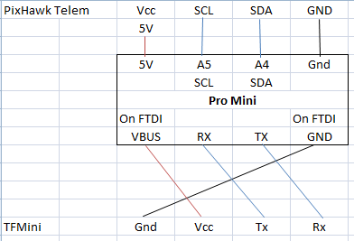
Here is a schematic because a photo is not clear. It is exactly like your photo except my Pro Mini has A4 and A5 in a different place and the FTDI connector is flipped. It is a Funduino.
Vcc comes from the telem port of the Pixhawk Mini. It provides a clean 5V. The TFMini gets its supply from the FTDI pins on the Pro Mini.
I have powered the TFMini from the FTDI, the same as when connected to the console, and it does the same.
RX (D0) and TX (D1) to the TFMini are not the FTDI Rx and Tx.
That does not seems ok.
The Pixhawk does not supply enough current and I dont recommand using it.
The Arduino and TFMINI must be fed using a3Amps UBEC and all ground connected = UBEC-Arduino-TFMINI-Pixhawk Mini
It works! I apologize- I thought I had connected another power supply and tested it when you first suggested the PS, but obviously not. It is now not reading correct m but that is just a matter of fixing parameters which I can do. Thanks again.
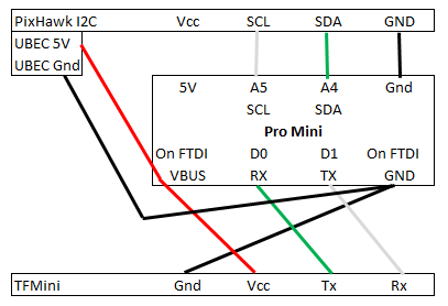
So I confirm; TFMini to Pro Mini to I2C splitter of Pixhawk Mini with a UBEC power-supply and a modified Sketch works. Tested with ArduPlane V3.8.4 and Mission Planner. I connected the +5V and GND output of a motor output channel (which is also directly connected to the UBEC) to the TFMini and Pro Mini +5V and GND. And removed the +5V from the I2C connector. Schematic is now:
@ppoirier So another question arises; there is a power saving function in ArduPilot, RngFnd_PwrRng, how does it work and how can I make it effective with the UBEC PS? I need to conserve power. The TFMini and Pro Mini are using 118mA. So that would use 120mA.hr in an hour flight which is significant if I could turn it off for 95% of the flight.
I am using it in a plane which I glide for some of the mission so only need it for the last 10m of landing run to round out.
I think this function is for PWM mode only, that is not the case here.
If really needed, you could use a relay pin from FC linked to aux. channel to shut off power on a controled UBEC like this one:
@ppoirier I received the TFMini, wired it up to the Arduino with your sketch, and connected it to my pixhawk via I2C. I enabled the rangefinder as Maxbotics I2C and changed primary alt measurement to rangefinder from barometer. I disabled the GPS and the GPS prearm checks. My alt measurement is much more accurate and precise than it was before. My issue now is im getting a “PreArm: check range finder” error. Any thoughts?
@ppoirier Worked, THANK YOU!!! Weather is windy and snowy so no outdoor testing today. As for indoor with GPS disabled, were you flying in Loiter or Stabilize in your video above?