Helllo friends,
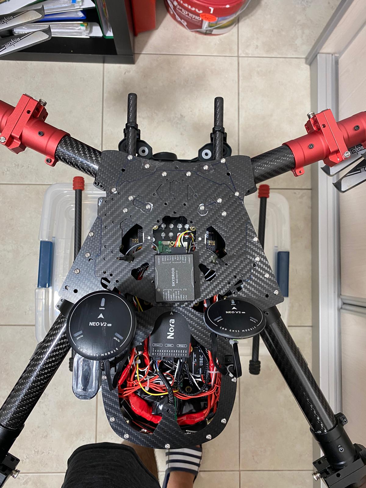
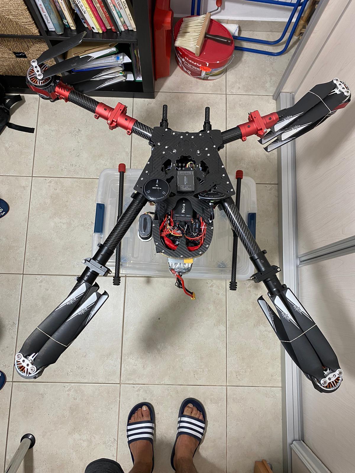
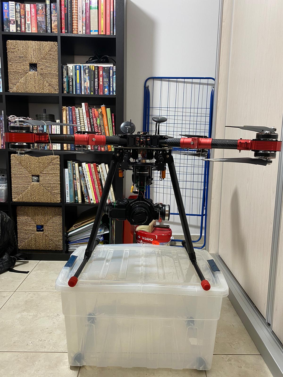
I’m looking for an idea on how to measure the center of gravity of my drone.
Any idea would be welcome.
Thanks in advance!

If your CG is fine, front and rear motors are at the same RC_OUT PWM (RPM).
I have the same problem:
1 Like
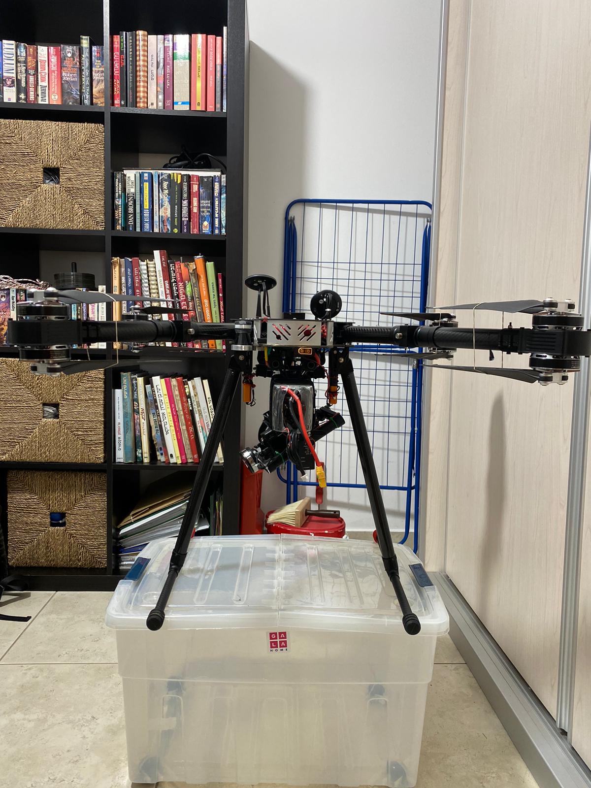
This is the worst frame to find the CG. The only way I know is to hold the plate where autopilot is placed from both sides and see where it balance. I had one of this way before and I got rid of it at the end as it doesn’t run the motors equal due it is formation.
1 Like
I think you can start from the midpoint at the roll and pitch axis.
You can do some flights on stabilize at lower altitudes and decide whether it is OK or not.
If it is acceptable, you can fly with LOITER mode.
Look at the motor output logs and if their mean value is close to each other it means that the CG is OK.
If it is not, move battery back and front and find the best spot.
Regards…
1 Like
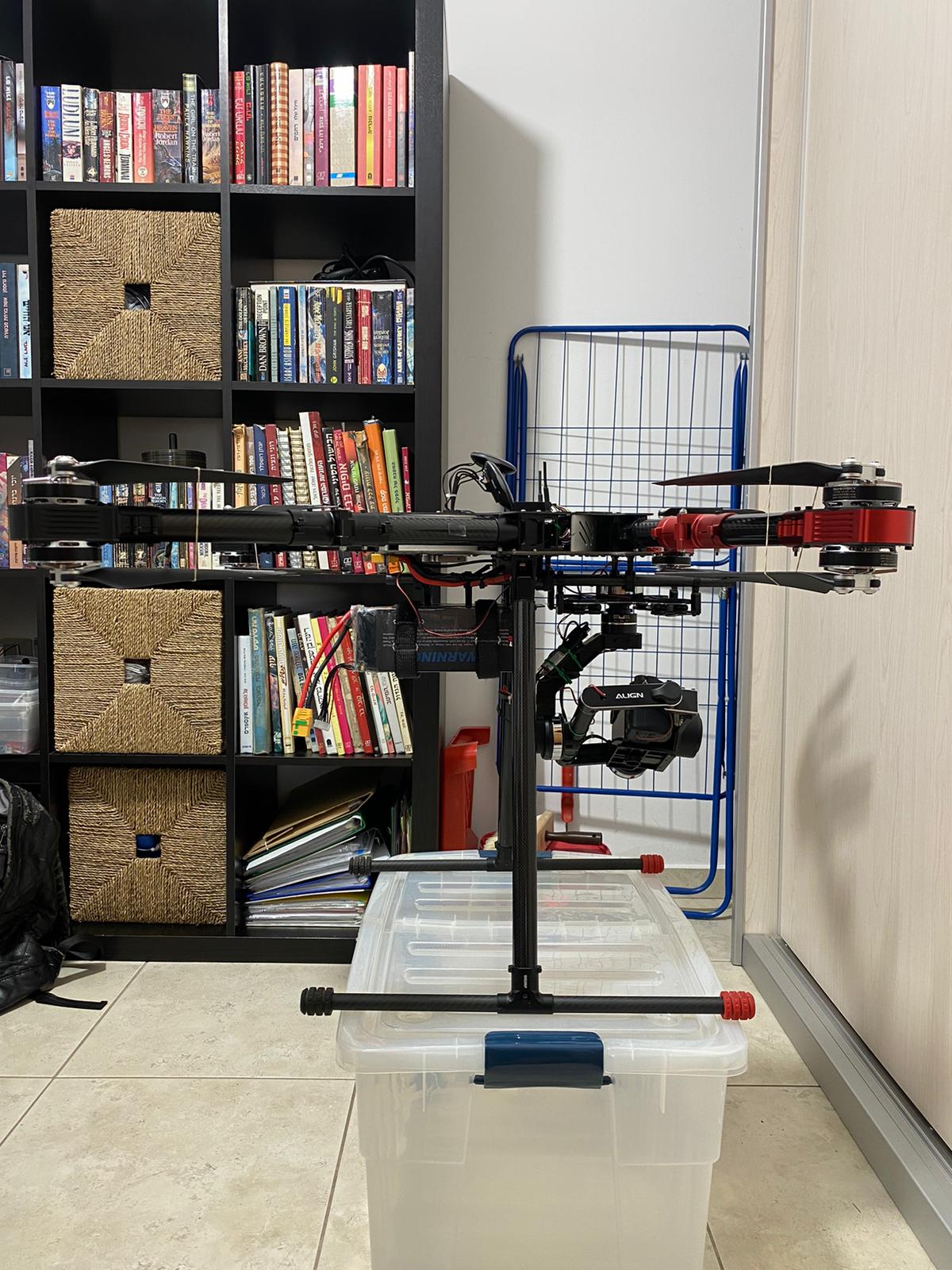
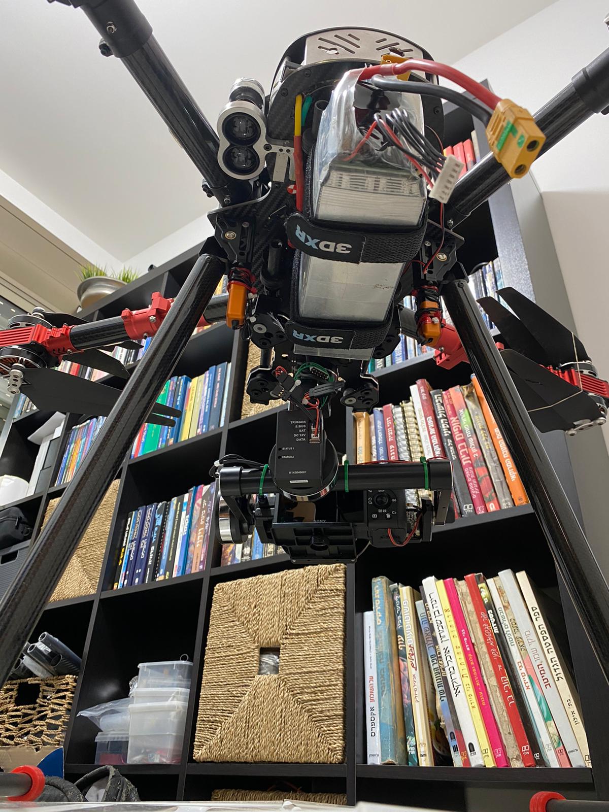
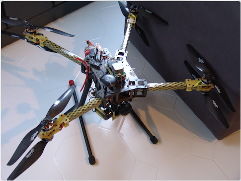
Thank you all for your suggestions, let me put more info. I found the CG and the quad fly beautiful, however when I added the gimbal it flipped forward even though I moved the battery back and the CG moved backwards.
Flipping
Log
More food for thought. Here are before and after (adding gimbal and camera) graphs of Motor Outputs. The only other difference was a change in the ATC_ACCEL_P/R_MAX values adjusted as per the tuning guide for the additional weight.
W/O gimbal and camera (these came from Auto Tune)
ATC_ACCEL_P_MAX,70433.22
ATC_ACCEL_R_MAX,75180.31
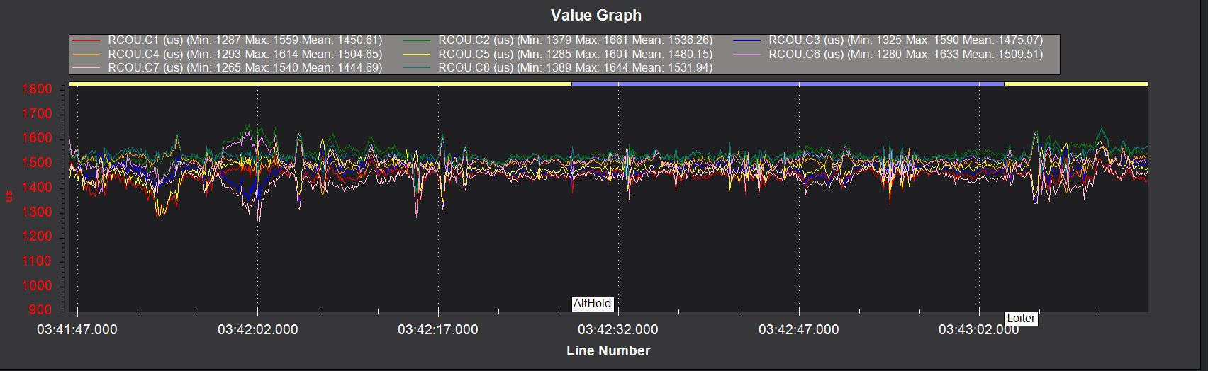
With gimbal and camera (added ~1550g)
ATC_ACCEL_P_MAX,53530
ATC_ACCEL_R_MAX,57137
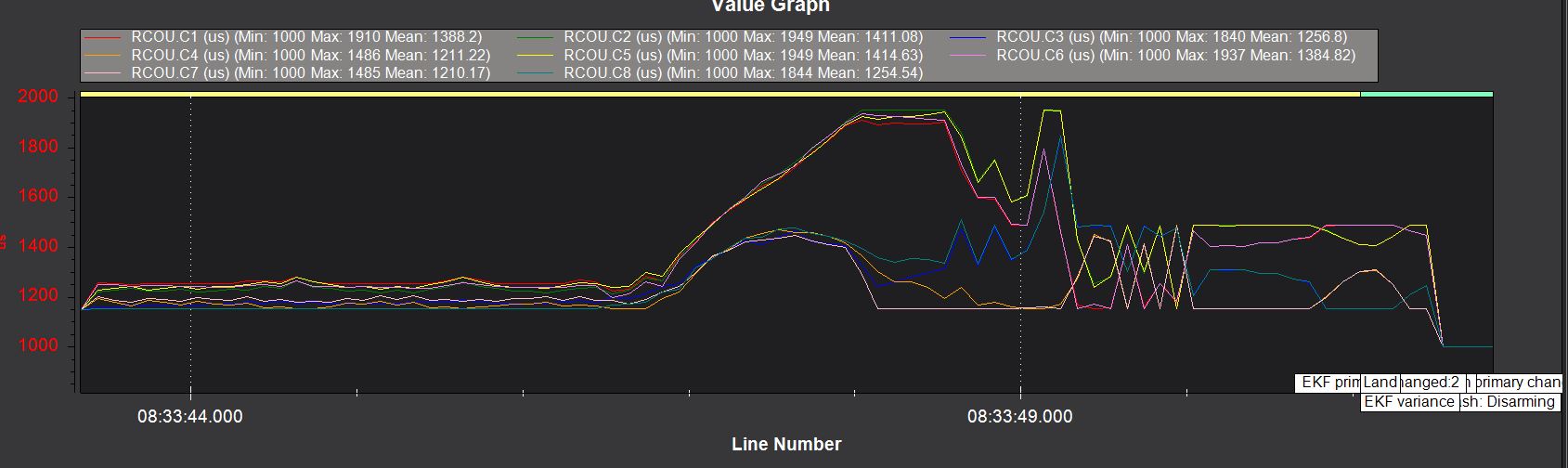
So it was flying great with plenty of power and very good motor balance. In the “With gimbal and camera” graph the front motors are commanded to max and the rear motors lag and it tips over.
My thought is to make another attempt at weight balance and set the ATC values back to “as tuned”. But admittedly I don’t have much experience adjusting these values based on added weight.
1 Like
@gnitzan
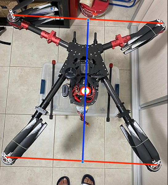
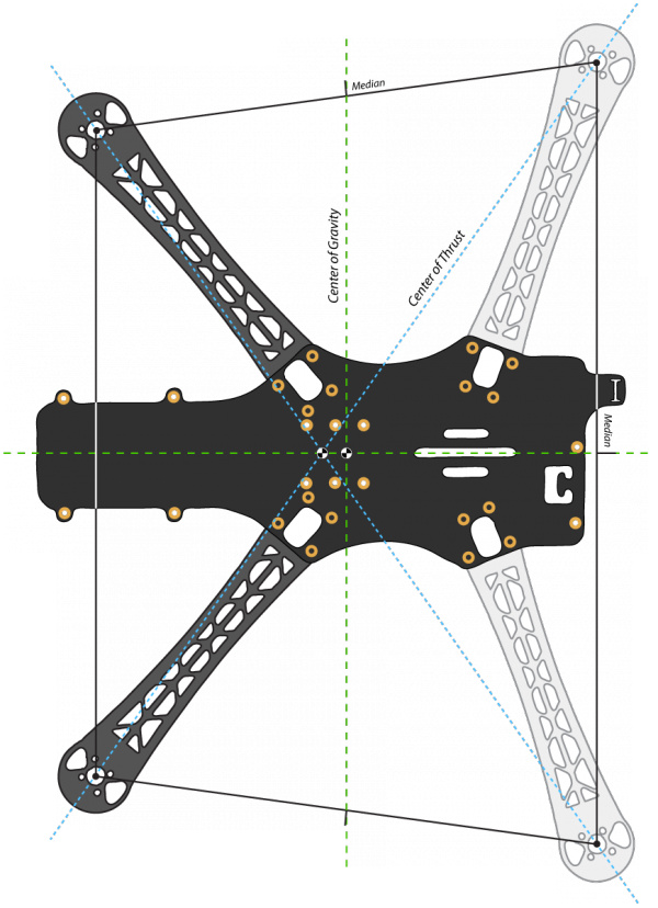
If you remove the top props and put in a single tall screw…tallest you have in each motor.
Then take a string and tie it around one screw and then go over to the next motor thats a diagonal to it and wrap the string around that screw and then go across to the next and so on.
Like this.
If you pull the strings tight it will give you the center.
This is the center of thrust or in affect the CofG.Then once you know this location. Take some masking tape and put in on the frame and then with a marker mark the CofG.
From that point on you can use that point to lift the drone and see if it’s balanced.
Remember this doesn’t mean it’s the location of the flight controller. While it’s ideal to place the FC at the CofG it doesn’t happen that often. Especially on these types of frames.
But this will give you a simple way of figuring it out.
2 Likes
Two other methods
Put one leg of the landing gear on a weight. The other on the table at the sane height. Then turn the drone 180°. If it is the same, the cdg id on the midle.
You can also place the drone on a round carbon fibre arm. Move the drone forth and back and you will find a point wich is in equilibrium. This is the cgb on this axis.
3 Likes
You can tie a string to one of the arms and then hang the quad copper from it. The center of gravity will be in line with the string. Do that on another arm, and the intersection of those two lines is the center of gravity.
Maybe take some pictures of the quad hanging from the string and then use mspaint or a similar photo editor program to extend the line downward and find the intersection.
The other ideas here are very interesting and would work pretty good too.
1 Like
Hello
If you have a scale, a precise one, it is pretty simple to measure CG position in X and Y : you make 4 measurements of the weight putting once at the time the tip of the landing gear on the scale, making sure the other 3 tips are at the same height, so that the drone is not tilting at all. Then with some math you get the position.
To measure the position in Z is a little more complicated, you meed to make it swinging like a pendolum, measuring the obscillation time and doing some math… as said more complicated but still doable
Bye
Use this method for finding the centre of gravity on a Dead Cat style frame: https://beta.ivc.no/wiki/index.php/TBS_Discovery_setup
To find CoG of anything, hang it from a thread attached to three different points at the ‘edge’ of the object.
To be more specific: if you have a complex asymmetric shape (like a copter) and you hang it from say the top of a motor arm, the CoG will be somewhere along a vertical line (a plumb line) from the attatchment point. Do this at three rather different points and the plumb lines will intersect (cross over each other) at the CoG.
In practivce not quiet that simple, as the mathematical line will go through the body of your machine but string won’t. SO, you can use a camera and draw lines (vertical) extending from the hanging thread (the thread is also exactly vertical ), or hang an actual plumb line in front and sight along it. I’m sure you get the idea.
good luck
2 Likes
Hello:
As a retired pilot, I still use the formulas I was taught for finding C.G. when I fly multi-rotors.
The best part of the math is it can be used for any frame type and you can also use it during frame building to position components, mostly the heavy ones such as the battery and gimbal.
You will need a scale that can handle a bit more than half the weight of the proposed frame gross weight, because you will be measuring weight from multiple locations, at least two. Some measuring tools, I use a framing square and tape measure and possibly a few pieces of thin wood.
Once the frame is put together and on the landing gear, in the OP’s case, set the frame on a table and determine the forward most part of the frame. In this case, the forward motors. Since the OP’s frame is tall, that’s what I use the framing square for, to be able to draw a line down to the table from the forward most motor bell housing. Don’t worry about the props sticking out.
That forward point on the table is now your “zero” point and all measurements will originate from there. (the reason you don’t have any weight in front of that point is numbers will be negative, so easier to work with only positive numbers.)
Now you have the start point, measure back to the landing gear. Notice on the OP’s gear, same as my symmetrical quad, the little rubber end pieces on the gear skids? Measure from the zero point back to the center of the forward rubber piece and the center of the rear piece. Write down those numbers. Those are the start of the C.G. calculation.
The process for calculation is to weigh the front skid tips, then spin the frame around and weigh from the rear skid tips. I normally have to use a flat stick, something like a wood meter/yard stick across under the skid tips because the scale I use isn’t very wide. I also support the non-weighing frame end at the same level as the scale with a block of wood and another stick.
The formula is simple:
ARM X WEIGHT = MOMENT
Arm = the distance from the zero point (we have 2 for our calculation)
Weight = self explanatory
Moment = the definition escapes me at the “moment”(it’s a physics term)
With the weighing points, once multiplied, we add the two moments together and divide by the total weight = C.G.
Here’s my quad frame Weight and Balance form from an Excel spreadsheet:
181119 WEIGHT AND BALANCE
	DEAD CENTER
	332
	WEIGHT	ARM	MOMENT
FRONT 1251 200 250200
REAR 1253 467 585151
		333.6
		2504
Since this frame is symmetrical, I measure back from the zero point and can identify the physical center of the frame, the “332”(mm) number. The “333.6” number is the calculated C.G., so pretty close, just aft. Notice the weights of the front and rear - 2gms difference. Since the rubber skid tips may or not be perfectly aligned on both skids, there’s always going to be a margin of error. If I can get the frame within 5mm of perfect, I’m satisfied.
Now the OP can use the center of motor thrust as his center point and determine where the C.G. is.
So one day we find ourselves building a DYI frame and want to get the C.G. close even before we start mounting all the normal gear. As I said, the battery and gimbal are probably the heaviest items. If we have the frame and gear layout done - this is easier with a symmetrical frame because you can leave off things like the motors and ESCs, you can setup the C.G. numbers and weigh the frame as is. From there, weigh the battery and gimbal with wires if you can.
Make the C.G. calculation using 3 lines of basic frame, battery and gimbal. But the idea here is to find the “ARM” that works for the battery and gimbal to put the C.G. in the center. The gimbal will always be more forward than the battery from center since it is lighter. I fly my quad frame as a " + ", so I mark the front arm every 10mm. After positioning the battery where I want it in the rear, I simply move the gimbal along the front arm, weighing each change at the new ARM position, until the C.G. is in the center. Generally all the rest of the gear is light and will be close to the center, such as the FC, on the frame, so you do not have to worry too much about those items.
You can also use this same formula to calculate a lateral C.G. as well. And don’t forget to account for any weight you put on the scale before you zero it.
glacier051 pretty much spelled it out. I’ve used two scales or one scales on many vehicles and that has checked out very well with other methods. To find the CG waterline location (z-body axis) I just put the vehicle on its side (roll it 90 deg) and use the same scale approach. As has been mentioned, you might have to create some kind of jig or frame but it’s pretty accurate.
Regarding the chap that asked the original question
Oh, no! That’s a sad news to hear. He was a good guy! RIP.