I realize this is a very old thread…but I just implemented a setup with two different receivers.
I have an RFD900X that streams PPM to the plane. I’ve also added an FRSky XSR set up for PPM.
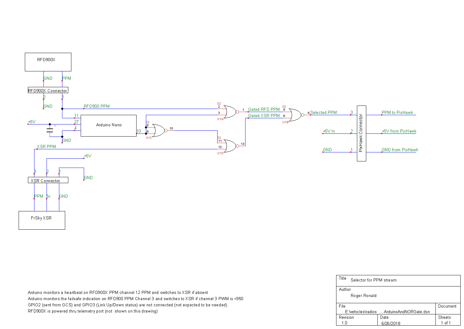
I programmed an Arduino Nano that watches the RFD900X PPM stream.
The Nano looks to see that there is a valid PPM stream.
The Nano checks channel 3 to make sure the throttle is not in failsafe
The Nano check channel 12 to see that there is a heartbeat from the RC transmitter (any hardware problem or a switch on the TX will kill the heartbeat)
If any of the above conditions go false, the Nano switches to the XSR. If all is good (and the TX switch is set to the RFD900), the RFD900 is selected.
The RFD900X is set for 12 channel PPM and is connected to the ground-side RFD900 with a trainer cord. The XSR can only do 8. The PixHawk doesn’t seem to care that the quantity of channels is different when there’s a change…channels 9 thru 12 just drop out when the XSR is selected.
I use a NOR gate connected to the Nano output for the actual channel swap. Even if the Arduino goes wrong (dies, locks up, etc.) the NOR gate should still be connecting one of the two PPM streams.
Much of my motivation is to minimize the odds of seeing my plane circling in RTL or running Auto with the realization that my RC control path is dead. With this approach, the only single point of failure for RC control is the NOR gate in the plane and the FRSky X9D transmitter. And…even if the TX fails…I might be able to borrow another transmitter at the field, program one channel for mode (AETR are fairly standard), plug it into my GCS and land.
Bottom line is that you can achieve some level of redundancy…but it’s not super easy.
I don’t recall seeing any specifications on the data rate that a GPIO pin can support. But, it seems very unlikely that a GPIO pin would be capable of running fast enough to support SBus.
PPM works well. I’m doing 12 channels over the RFD900x with it.
There is a RFD900 thread on DIY Drones that would probably be more suitable for these questions. RFD monitors and responds on that one.
I used an arduino nano with long pins and a proto board between the pins to mount the NOR gate and connectors.
A little circuit card would be better (cleaner, easier to duplicate, lighter, and probably more resistant to damage than soldering wires to the pins). I’ve got the above schematic in TinyCAD and it’s dead simple, but I’ve never created a board design. If someone wanted to volunteer, it would be appreciate.
It’s not that difficult to wire up. I can dig into the plane and get a picture of the switcher. Or…I may just wire up another one since I’m building another plane.
I am not very skilled at version control and such, so there’s a small chance that I don’t have the correct library…but I got the code to compile w/o errors on Arduino 1.8.5. with the attached library.
RR
Definitely some “older” tech. I learned digital electronics from Don Lancaster’s TTL Cookbook around 1980 when I was trying to build a “home control” interface for an Apple-II computer. That lead to a Heathkit Oscilloscope…and eventually, a job assembling mini-computers. A few years later, I was an I/O architect for supercomputer systems (multiple Cray J-90s and C-90s).
But, that most basic old and simple function still has its place. I never want to be holding a transmitter that doesn’t work while the plane circles in RTL …waiting for the battery to run down and crash. The odds of a NOR gate failing are vanishingly small…and either of the two possible inputs connects a radio.
I am going to modify my setup. Currently, I connect to the RFD900 thru the FrSky trainer port and a cable. But, that’s a pain (the ground station has a tracker and is moving/rotating…plus I like to be able to walk around). I lost the XSR connection on one flight…and it took way too long to plug in the cable to connect up the RFD900 during my panic. So I’m going to try get one XSR to talk directly to the plane and another XSR in the ground station that connects to the RFD900x uplink.
I mixed up my own antenna tracker. My requirements were a bit different.
My tracker has a continuous rotation pan servo. So it has no position feedback. The tilt servo does 90 degrees.
Since it’s continuous rotation, the heading must be determined from a compass. All the electronics and the battery are on the pan section of the tracker. There isn’t any need for slip rings, etc.
The software is fairly easy…the GPS on the plane is already sending a position in the telemetry via the RFD900. I just tapped off the RFD900 RX signal to grab it. The mavlink library code captures the bitstream and gets the plane’s position and altitude. The tracker gets it’s own position and altitude from GPS. The bearing and tilt angle to the plane are calculated. Then the tracker attempts to minimize the delta between its heading and the bearing to the plane…and commands the correct amount of tilt.
I’ve only flown with it once, but it seems to work fairly well. I have a raspberry PI in the groundstation and the telemetry is logged there…and sent via WIFI to my laptop.
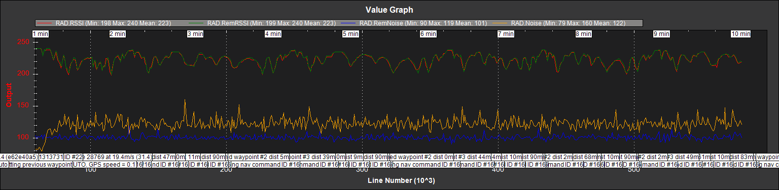
Here’s a plot of RSSI/REMRSSI and the noise numbers during that flight. I’m still not perfectly happy with the REM Noise, but the margin is now pretty darn good.
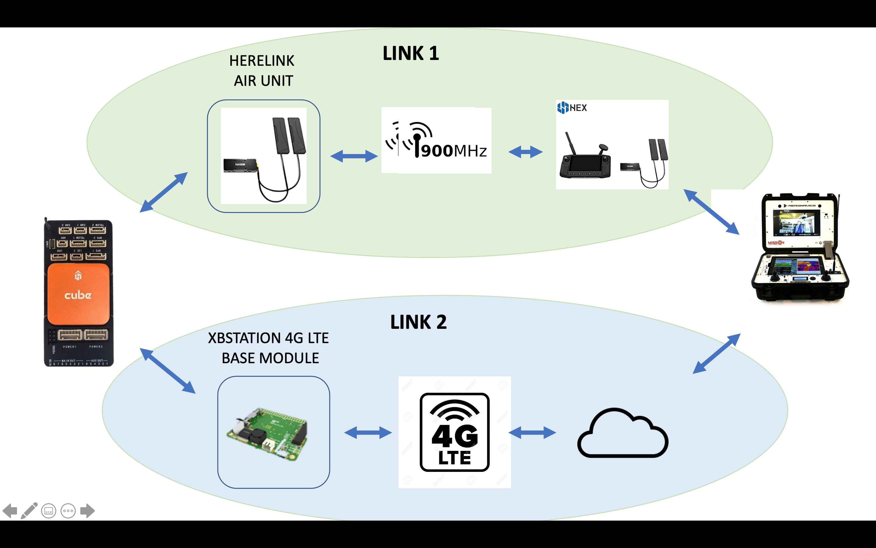
I now use 3 RF links. Receivers for link #1 and link #2 bind to the same TX channel.
FRSky TX to R-XSR in plane (8 channel PPM)
FRSky TX to R-XSR in ground station (12 channel SBus)
Ground station to plane via RFD900x (12 channel PPM, I built a converter from SBus to CPPM for ground station)
Link #1, directly to the plane is a standard connection using 8 channel CPPM. Links #2 and #3 transport 12 channels of data. The first hop is on the ground. Since FRSky only supports more than 8 channels with SBus, I have to go SBus for link #2 and then convert it to CPPM (which is all that the RFD900x supports).
At the plane, the previously mentioned circuitry selects one stream or the other and provides it to the PixHawk.
Telemetry was disabled during the binding process for link#2. I currently have minimal FRSky telemetry for link #1 (just the built in RSSI) and plan to add MAVLink to FRSky telemetry on this link. This will give me a redundant telemetry link since the RFD900x implements full bidirectional telemetry back to a laptop (connected thru a Raspberry PI with WiFi on the groundstation).
I still don’t understand why this shouldn’t be implemented within the Pixhawk. Adding external hardware adds an additional single point of failure. Is it really so hard to make the failsafe logic check a secondary R/C for a valid signal while doing RTL? I am using a 433 system for both telemetry and PPM to get the range I need. When the 433 link is lost the Rx is set to produce no PPM pulses which triggers failsafe. I would really like to be able to use 2.4 as a backup. In fact I use 2.4 for relay from the controller to the 433 system in the ground station (failsafe set to no pulses also). When the aircraft flies back to home after a 433 failure, I would very much like to be able to land it. As it’s a fixed wing, and I’m operating on uneven ground, autoland is non-trivial or impossible. I wouldn’t even need an additional controller, just a Rx onboard the aircraft that was also bound to the controller, plugged into the SBUS port. This would be a very valuable safety feature for me.
I too am very interested in multiple redundant receivers being directly supported on the Pixhawk by ArduPilot. I’d rather not have this happen… https://www.youtube.com/watch?v=GrrKvhtr5UQ

 The odds of a NOR gate failing are vanishingly small…and either of the two possible inputs connects a radio.