Great you can read .OBJ.
3DS MAX can import also .OBJ. And your design is even smoother and use another method.
That’s great. That means we can take advantage of both 3DS Max and OpenSCAD for designing visuals and 3D printed components.
Now I just need to decide what I want to build 
I hope a BlackMark
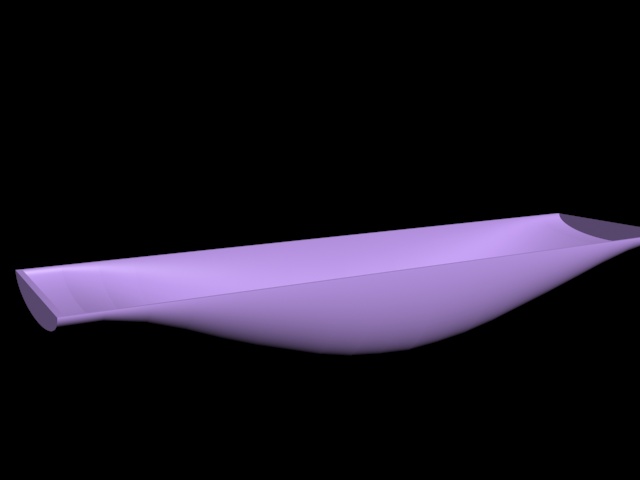
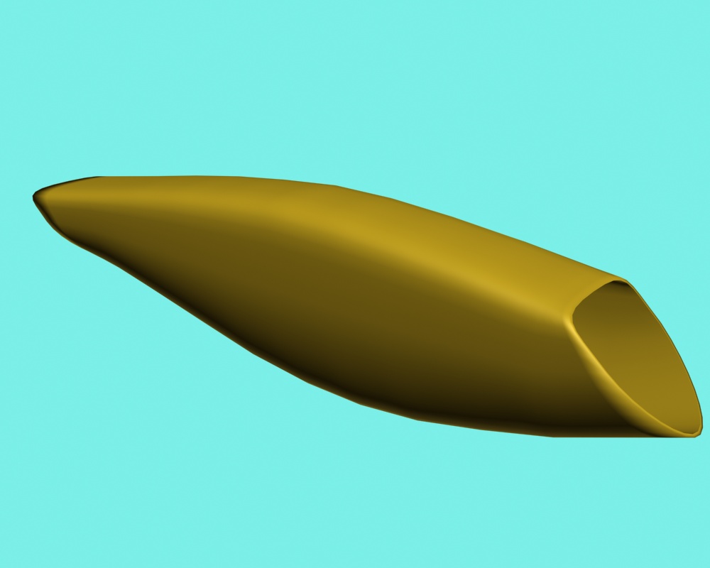
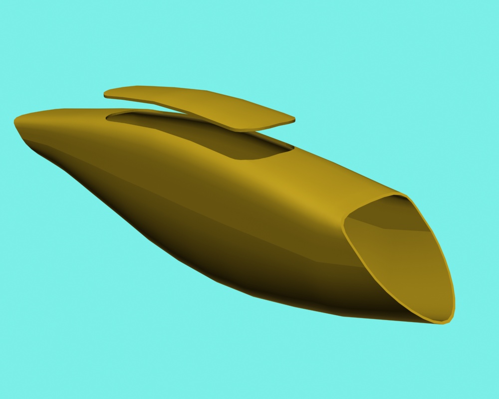
About your perfect specimen of the fuselage I was challenged to do my verry best.
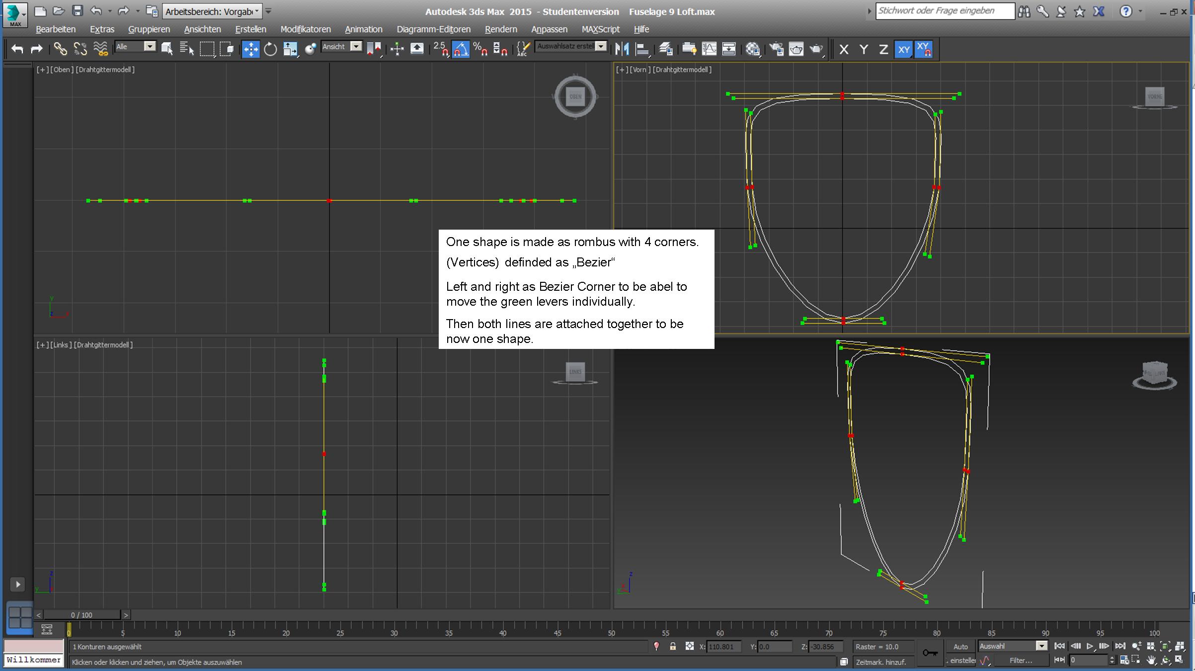
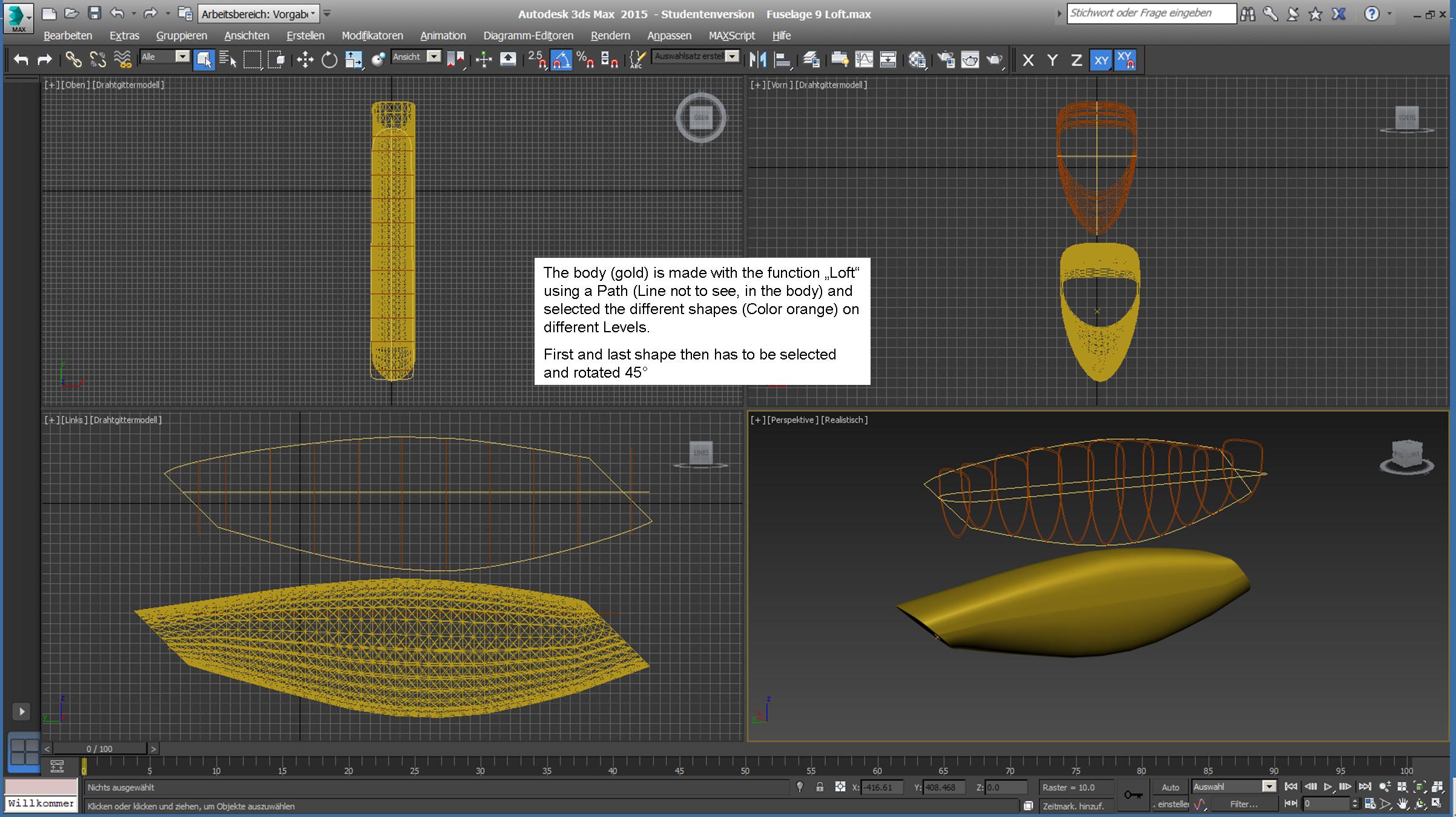
An so I tried another method to create it. This is even easier to modify or adapt.
https://drive.google.com/open?id=14Ma9MIlUM7-pZg3d7FBR1yq78Fd
Nice! What techniques are you using to define the shape?
Can you specify a very thin wall thickness, such as 0.4 or 0.8 mm?
I get a 404 on your gdrive link.
Here the link again:
https://drive.google.com/open?id=14Ma9MIlUM7-pZg3d7FBR1yq78FdK8L6U
Seems to be an error at the end of the link.
For further images, can you read PowerPoint files?
I use it for Print Screens and poste processing as the images above.
Yes with the last methode it is constant around the shape, but can your 3D Printer this?
And it would be sensible like an egg or may be elastique?
That’s a very powerful tool, and it works a lot like the OpenSCAD program I found.
Yes, I can view PowerPoint files.
A thin skin plus internal structure is the way the 3Dlabprint guys do airplane parts.
The skin and main spar are a single pass with .4mm nozzle, the ribs are thicker, but not solid.
I’ve done a lot of thinwall vase printing, but haven’t had much luck with their STL files, they’re all non-manifold and the slicer they use is proprietary.
Hopefully I’ll be able to print my own thinwall designs though.
Yes with internal structure. But sometime difficult when a lot of support structure is needed and not easy to clean. The fuselage needs to be printed vertically. And longitudinal ribs are then easy but not intersections.
Intersection could printed separatly and then glued in by the opening. One end on the base printed, the other on top also glued. I use Araldit for PLA.
Here a test how to make a cover with boolean functions.
Yes, one of the biggest challenges in designing structures for 3D printing is eliminating the need for support. The 3Dlabprint guys have done a great job of that with their designs, but it does take a well-tuned printer to print the thin walls properly.
I try to break parts up into pieces that can be printed with no support. It looks like this fuselage could be done as top and bottom sections with integral longitudinal spars, with bulkheads printed separately and glued in prior to joining top and bottom.
I could try to integrate the pars into the shape for the shell. But then I should know first the wanted thickness of the shell to avoid to do it later again. How many spars are needed an which dimensions?
I’ll need to do some test prints to determine the skin thickness and size/number of spars.
I can generate and add spars pretty easily in OpenSCAD for testing. I’ll soon print a test part in PETG and will let you know how that looks.
I’m close to make the first test in the Rack. Is this still valid for a copter Tailsitter with Plus-Frame?
FBWA flight with qassist enable.
the 3 position switch work perfect, transition are OK. This depron model does not have airspeed but assistance run very well. Assist speed was set to 6m/s.
Most of the time I would not be able to say when when assistance is triggered or stopped, only on a sharp turn the transition cause an attitude change. Assistance brings a lot of stability at low speed, this light plane is even more difficult or impossible to stall, only throttle has to be managed. Great result.
I did not found any information in the PR about the bitmask associated to q_tailsit_options.
1 Like
Congratulation. Great performance. Does this work also with a Plus-Frame?
Great, thanks for testing!!
q_tailsit_options is not in that PR, setting it to 1 allows you to use Qassist with motors only. This leaves the plane controller in charge of the control surfaces and copter controller is used for the motors only. It also uses the the plane integrator. This means you should be able to go as fast as you like in Qassist because its the control surfaces that cause ‘speed wobble’. Leaving the plane in charge of the integrator also means you should be able to seamlessly switch Qassist on and off. Switching to the copter integrator (as it does now) can cause a step as the new integrator builds up. In your case if it is switching very smootly this suggests you have done a excellent job of trimming in forward flight.
Yes, frame type 16 is quad-plus with no yaw torque in current master.
So you can have counter-rotating wing motors (left/right, 1/2) and top/bot (3/4).
Looks great! Does the log show the estimated airspeed and when qassist is active?
Ctune_aspd gives a curve that look good but I do not see when qassist is active, @iampete ?
yes, I think so. Qassist enable motor stabilization with the help of copter controller so it does not depend on the frame type.
What makes this switch?
On my vectored Tailsitter AHRS_ORIENTATION was 0. For copter Tailsitter in SITL you set it to 25.
My FC is mounted flat on the wing (horizontally in FBW Mode) What is correct for the Copter-Tailsitter?