I will collect a tlog. It should be interesting to look at. At one end of the property are power lines that cause a temporary compass variance error that quickly recovers without issue. With previous setups that area couldn’t be approached without a mission ending in failure.
Any chance of a dataflash log? There is much more to see in these logs.
Yes, I will collect one some time this week.
Very nice rover Vincent! Yes, your antenna is not that close to the alternator. Mine is closer. I didn’t have any time yet, but i hope i can try to do something with it soon.
Possibly not your case, but see this.
1 Like
That’s really spectacular! Do you think if I can test this way with a smartphone compass? Or the only best way is to use an analog compass?
Good Morning,What’s your test results in saturday?
Nothing yet. Unfortunately I did’t have time for that on the weekend. If i have any results, I will post here immediately.
Analog compass:
-Very well known instrument during centuries.
-Cheaper and more simple than a smartphone.
-No bugs, no software, no battery.
-No new software release correcting some bugs but introducing others.
-Sensitive and reliable.
-You can slowly move your motor by hand and see really what is happening.
2 Likes
This post describes an iPhone app that allows you to measure the magnetic field
Facing the same problem you did (in fact, probably worse, since my deck is also electrically powered) I ended up with a large mast. https://photos.app.goo.gl/rrNTHjFD2JTFJ7Kt6
The mast presents operational challenges since it prevents the mower from mowing under trees. I’m working on switching over to a dual GPS setup and using yaw from the 2 GPSs. Several threads on this forum about that including Use Heading from Dual GPS - #53 by Christopher_Milner
1 Like
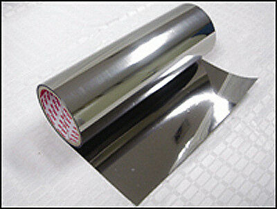
With that size, you can try a mumetal inverted umbrella between motors and compass:
1 Like
Can you please explain how mumetal (or any magnetic shielding) would help?
I’m not sure if it would help in practice, but, since you have space, you can:
·Make a mumetal cover around the motors. You can leave out the controller (with its internal compass).
·Place a wooden plate or similar with mumetal sheets below the GPS/compass (between it and the motors), moreless like an inverted umbrella.
You want to maintain the earth magnetic field, but decrease the influence of the motors.
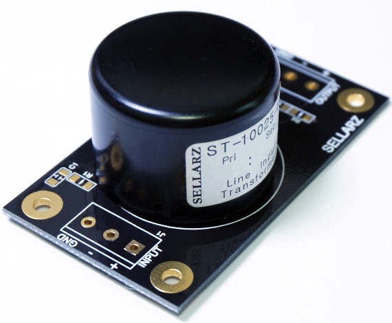
I’m not sure if this i useful. This a mumetal shielded input ac line transformer used in audio:
Hi guys! Thank you for the lot of advices! Unfortunately I didn’t have time for doing large experiments, but I’ve found an analog compass at home and I checked the mag field around the rover.
It’s really distorted even with fully turned off electronics. I think this caused by the engine’s flywheel which contains strong magnets. And of course the motors too. So I will try to put the antenna higher, and turn on the offset learn feature in pixhawk.
We’ll see…
While that might help it would be expensive. We use MuMetal to build induction coils and it’s very costly!
30x45 cm less than a Pixhawk.
My experince with a 1/10 sacale rover and a 450 helicopter (both single electric motor):
·Calibrate with motors out. Don’t calibrate with motors in place.
·If not arming, initially move motor slightly till getting permision (audible), and later simply permit arming with compass problem.
See this video:

Rover starts even placed opposite to first waypoint.
That is a good price!
Calibrating your compass with the motors out is sort of defeating the purpose… If you can not calibrate with the motors in place then you will never get a reliable heading from your magnetometer. Sure you can pass your calibration tests but the magnetometer will output garbage when everything is back in place. If you are having issues with the proximity of the motors when they are not operational, then you either have a poorly designed PM motor that does not adequately contain its magnetic field, or you have ‘soft iron’ distortion due purely to the proximity of low permeability material. Any vehicle that contains significant amounts of ferrous metal will distort the local magnetic field and make it hard to differentiate orientation based on the output of a magnetometer. It is not the fault of the magnetometer and there is no kind of ‘super duper’ magnetic sensor that can get around this. In these cases, the magnetic field simply does not unambiguously indicate orientation. Anyone suggesting that adding ‘mu-metal’ or ‘permalloy’ in these situations, does not understand what is happening. The very properties that make these materials useful is the exact same thing that makes them distort magnetic fields. They are essentially, the very best materials available for distorting magnetic fields! The more of these materials you have in the presence of your magnetometer, the worse your magnetometer will perform. There is a very limited use case for these materials where you have a strong but compact ‘hard iron’ source (magnetic sources - this can include high current DC cables). If you can use a small amount of these materials to short circuit the magnetic field emanating from the source, and if the amount you reduce this is less than the interference you add, then you can improve the situation. I do not see this being useful in any of the scenarios listed here.
1 Like
Watch how the rover (which had been calibrated with motor out) starts in above video: it is placed opposite to first waypoint, and at start it has no orientation help from the GPS. It turns 180º and heads the first waypoint. It completes the rest of the mission succesfully.
1 Like