In your ground station, in the full parameter list, there should be an option to export or save the parameters to a file. We need that file to see what the setup is.
ardu status.param (13.6 KB)
Chris,
Can you use this file I recorded on ground station as full parameters list?
Guy,
I think I figured out your problem. Please make the following changes on the full parameter list page. Remember that you have to write the changes to the pixhawk for them to take effect.
The parameters are SERVOX_FUNCTION.
SERVO1_FUNCTION=33
SERVO2_FUNCTION=34
SERVO3_FUNCTION=35
SERVO4_FUNCTION=36
Since your ESC is connected to channel 8 then
SERVO8_FUNCTION=31
This should make your servos work.
Chris is right. It is easier for us to figure out issues when we have a parameter file. Thanks!!
ardu status.param (13.6 KB)
Chris,
Here is the parameters’file I recorded on the ground station. Hope that would you find what’s wrong.
ardu status.param (13.6 KB)
Bill,
I did the changes on every servox_function as you suggested. Still no response from servos.
Would you analyze the parameters I attached?
You must not have written the changes to the pixhawk. The values were the same as before. On the right side of the screen on the full parameter list page there are 4 buttons, load, save, write params and refresh params. Be sure you click on write params after you make the changes to the parameters. So when you change any of the values for a parameter the box will turn green. Once you click write params, You will know the parameters were successfully written to the pixhawk because the green box will disappear.
Bill, I am worried here about the entire setup and what has been changed. It had servo 1 config’d as aileron, 2 as elevator, 3 as RCIN3, 4 as rudder. That is airplane configuration, not helicopter. I think I would go to the full parameter list and reload the defaults and start over to make sure there is something that we did not miss going thru the list. It looks to me like RC6 and RC7 have calibration problems, and even SERVO8 is set to RCIN 8.
That’s why I think I would force a hard reset of the params and start over on the setup.
@bnsgeyer Unfortunately, I do not know how to instruct a param reset with Mission Planner, as I do not use that ground station. I just assume it has a reset to defaults button like APM Planner2 has.
I think resetting to defaults will force a re-calibration of the RC. And then get a param file after that to check which channels got calibrated. If a PPM encoder is being used, my experience is that they are not all the same and proper calibration of the range on Channel 8 will be required to get the heli’s engine to start.
If we have a wide variation in range on the 1-8 channels, then we have either a RC problem with mixes in the radio being used. Or a problem with the PPM encoder.
It does. There’s a ‘reset to defaults’ button on the config screen. An alternative method is to load a different firmware (plane, rover) and then reload trad heli. This will completely clear any parameters.
@ChrisOlson I don’t see an issue with the RC calibration. RC 6 and 7 having a small range between min and max just means he didn’t have that channel assigned to a switch or didn’t actuate the switch. Looking at the ranges for all of the channels that matter, I think it looks fine.
I’m not that concerned yet with his setup and the integrity of his param file. It looks like he used a page in mission planner that adjusts the servo output function based on what he thought they should be. Let’s see what happens once he gets these servo functions set correctly.
Yeah, the bottom end of the RC calibration ranges looked consistent with S.Bus and that was somewhat confusing. That could be just in the PPM encoder. I went thru the whole param list as well, and didn’t catch anything else right off, but it seems I always miss something in those darn things unless I go thru it about 10 times 
Hopefully, changing the servo functions as you suggested will at least get the servos operating.
Chris
Bill
I followed the discussions between yours.
May I make a synthesis of the situation.
My Tx is in heli config without any swtch mixing
the Pixhawk is powered by the firmware V3.5.4 heli
The parameters confirm the frame is heli
Power supply is ok (5.2 V)
On pages set up, every signals up to servos output play well corresponding to the sticks movments
Prearm is OK
Arming is possible but disconnect after few seconds
The servos do not work
I did the changes to the servx_function without success
Should I increase the throttle signal 1000 to 2000?
Should I do the motor calibration?
Yours,
Guy
Let’s verify that you have the servos plugged into the correct outputs. In this photo, note that the SERVO outputs start at 1 in the middle of the servo rail. Going from left to right in the photo, the AUX pins are numbered 1 thru 6. Then the SERVO pins are numbered 1 thru 8. If it is a Pixhawk, after 8 there will be a SBUS out, then RCIN. If it is a Pixhawk2.1, as shown in this photo, then there will be no SBUS out on the servo rail.
The LF servo goes to pin 1. RF to pin2. Rear to pin 3. Tail to pin 4. In this photo I have the power from the servo battery going to pin 5, but this will normally be power from a BEC. Throttle goes to pin 8 (not shown in the photo because I have that hooked to S.BUS). RCIN to the receiver.
The ground pins on the servo rail are to the top of the Pixhawk, signal pins to the bottom. The power to the servo rail from the servo battery or BEC must be at the correct voltage for your servos. Please note that the power to the Pixhawk only powers the board. Separate power to the servo rail is required to power the servos.
Chris,
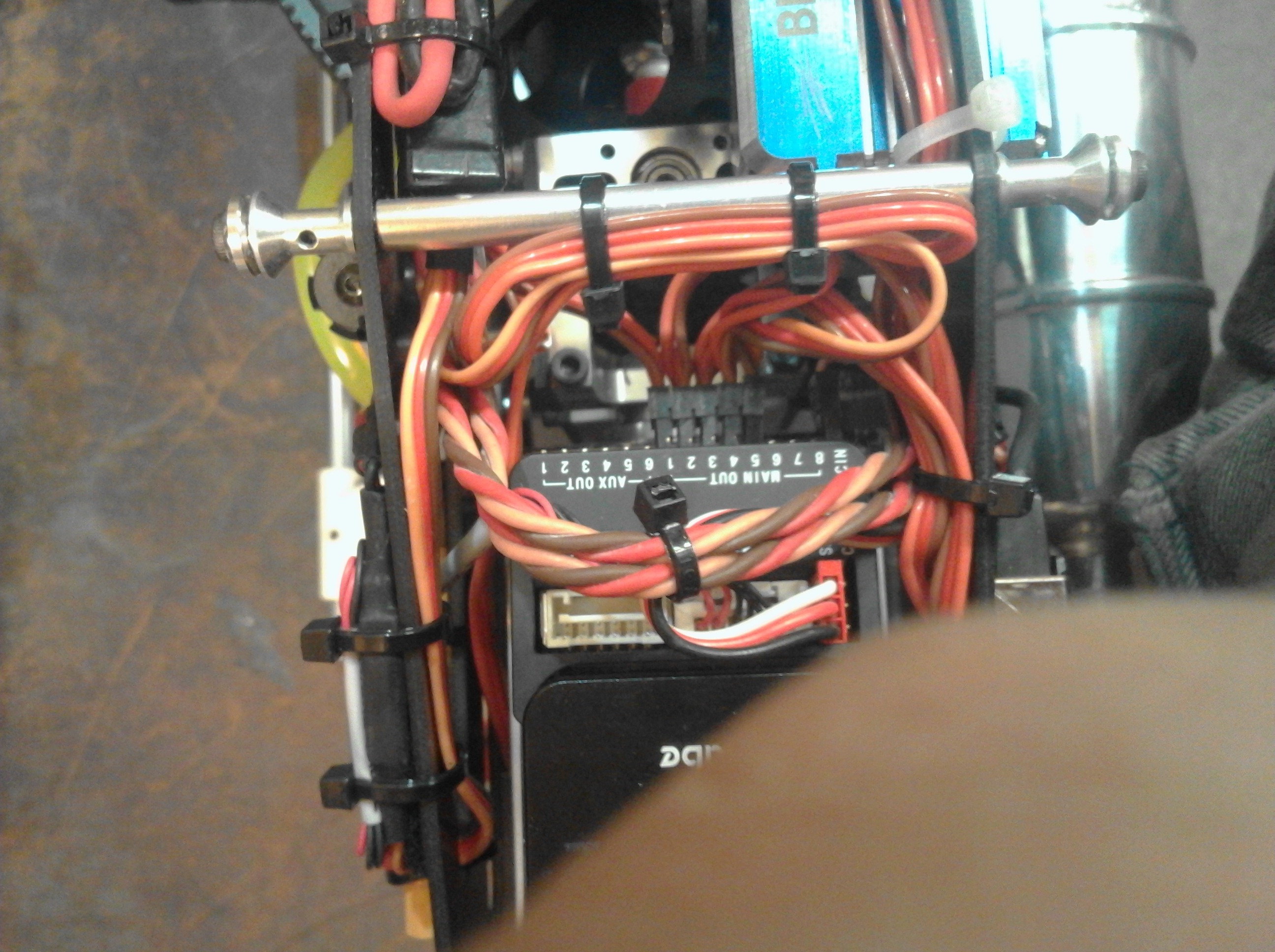
I send you the photo of the electronic board that shows:
The PPM input (top of the photo)
motors output rail. the heli motor with its BEC power is plugged at eighth output
Servos rail indicates outputs from 1 to five. Servos are connected as follows:
LF to pin 1; LR to pin 2; Rear to pin 3; Tail to pin 4
I have not plugged a power supply to the pin 5. Normaly, motors and servos are distributed on the same power rails.
Ground pins are at the bottom for mine and signals are at the top. Refer to the scheme.
The ower supply is given by the BEC (5.2 V); But, as you request, I will connect to sevo rails a specific power.
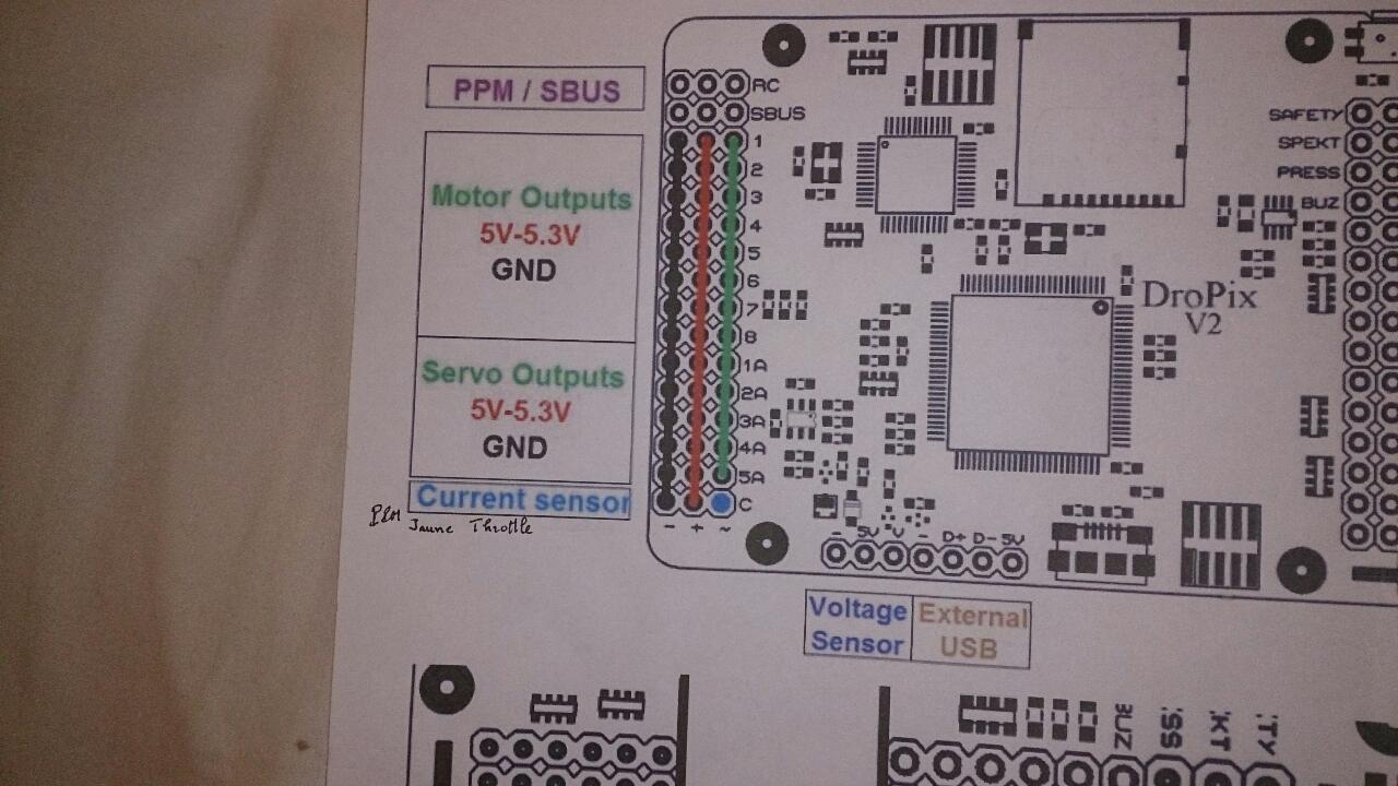
Ok, that is definitely a non-standard board that I have not seen before. Assuming it is consistent with the Pixhawk design on servo rail power, the power module that powers the board DOES NOT supply power to the servos on the servo rail. The servo rail must be powered from a separate source with voltage and current sufficient to power your servos. That is what the plug in the photo I posted on pin 5 does. It supplies power to the servo rail from a battery to power the servos. That power can also come from a BEC.
I’m not sure what the additional pins are for that says Current Sensor. But according to the diagram it is on the servo power rail, with a separate signal pin. Maybe the servo rail power is supposed to come from this Current Sensor? Perhaps somebody who is familiar with that board, or has used one, can comment.
You need to connect the servos to the ‘Motor outputs’. Whoever designed that diagram did it with multi-rotors in mind.
To use what’s called ‘Servo outputs’, which are really the AUX outputs in regular Pixhawk language, you need to enable them specifically. But don’t do that. Connect the servos to the motor outputs.
Chris and Bill,
I checked and I found the +V of the servos rail is not connected to the power supply while the Ground is well connected.!!!
I will restore the connection and will report to you.
Guy
I think that’s the way it’s supposed to be. The servo rail normally requires separate power supply. Otherwise the Power Module can’t supply adequate power for both servos and the electronics, and it will cause your electronics to “brown out” and crash your helicopter.
Hi Jakob,
Thanks to come for help.
Do you mean I should plug the servo 1 to 4 on the motor pins 1 to 4?
Yes. But you still need to provide an external power source.