Hi,
I want to share my bachelor thesis project, which is about integrated indoor positioning and trajectory control of quadcopter for indoor environment. The position control error is below 10cm, and 100Hz position estimator is fused from optical flow and my developed indoor localization system. All of them is running on Beaglebone Green with modified Ardupilot source code.
I would love to hear any feedback or advice. Any comment is appreciated. Enjoy!
- Video Demo: https://youtu.be/AmKh1lJENtE
- Gitlab (checkout branch Copter-3.5): https://gitlab.com/nghianguyen.automation/ardupilot-snsh.git
- Github: https://github.com/nghiajenius-dev/GradThesis.git
SYSTEM DESCRIPTION
The system consists of three main components:
- Indoor localization system
- Quadcopter system
- Guidance software
1. Indoor localization system (ILS)
The system aims to provide 3D position information of a moving object for indoor environment, or where GPS is not applicable. This system utilizes Time Delay of Arrival (TDoA) principle of Ultrasonic and RF signal, and is able to provide 3D position information at 20Hz with rms error at 2cm.
To establish such system, 5 ultrasonic receivers are mounted on the ceiling, and a wave transmitter is attached to a tracking object (quadcopter). When the transmitter periodically emits RF & ultrasonic signal, the receivers calculate TDoA of the waves to determine the distance from the tracking object to each node. After that, the estimated distances are sent to the tracking object to perform position calculation using Nonlinear least square (NLS) trilateration. The sensor network is managed by CAN bus, and sine wave detector technique is implemented to minimize position error.
For more details, please read my previous post.
2. Quadcopter System
To demonstrate the localization system and develop a position/trajectory controller, a 250-size quadcopter are used. The quadcopter includes a custom PilotCape for Beaglebone Green and a PX4Flow optical flow sensor.
The PilotCape has 3 main parts:
- MPU9250 IMU and BMP280 Barometer, reference from BBBMini and BeagleBone Blue project
- A transmitter circuit: CC1101 RF transceiver, and power amplifier for ultrasonic transmitter, and a microcontroller to manage transmission.
- External ports: Optical flow connector, serial port for microcontroller-BBGreen, and others.
Beaglebone Green on the quadcopter runs these tasks periodically with modified Ardupilot firmware:
- Trigger the transmitter at 20Hz, receive measurement results from sensor network and calculate 3D position using NLS trilateration.
- Combine localization result at 20Hz with moving velocity in X-Y plane obtained from optical flow at 100Hz. The project applied Kalman multirate estimator to combine two sensor sources.
- The Kalman output are filtered position and velocity of tracking object at 100Hz rate. This information is input of position controller that send angle command to attitude controller.
Integrated Indoor Positioning
The objective of this work is that each sensor source has its advantage/drawback. Specifically:
- Indoor Localization System: provides absolute position data with 2cm accuracy and don’t drift over time, but slow update rate (20Hz) and low resolution.
- Optical flow: provides relative displacement from velocity integration, it can reach higher rate (100Hz), but suffer from position drifting due to error in integrating process and gyro drift.
For these reasons, this project implements Kalman Filter multirate to integrate ILS and optical flow data, and provides object’s position and velocity at higher rate (100Hz) with lower noise, which is suitable to control a quadcopter position.
Calculate translational displacement from optical flow
Original reference article is here. Below is a brief description of my study.
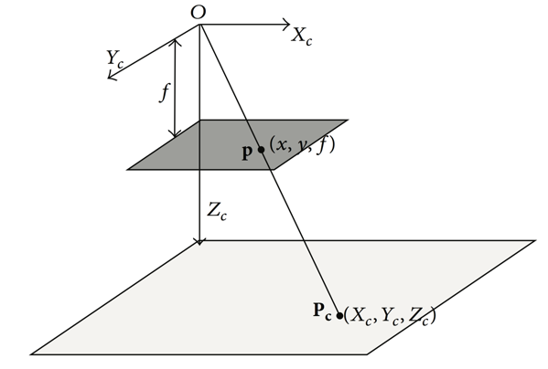
PX4Flow module is mounted facing down. Its camera has fixed focal length at 16mm. Therefore, by measuring pixel displacement and true Z distance, we can calculate ground true displacement of the moving object.

However, relative motion between the camera and object consists of translational velocity and angular movement. Therefore, the translational velocity can be determined using the simplified functions below:

Finally, 2D rotation is used to align the body frame with world frame of the ILS:

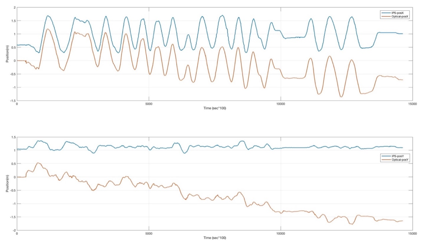
Displacement is calculated by integrating translational velocity over time. The result below shows the comparison between ILS and optical flow position.
Combine ILS and optical flow
MATLAB model, simulation using real raw sensor data and how to generate it to C library is on Github.

Position & Trajectory Controller
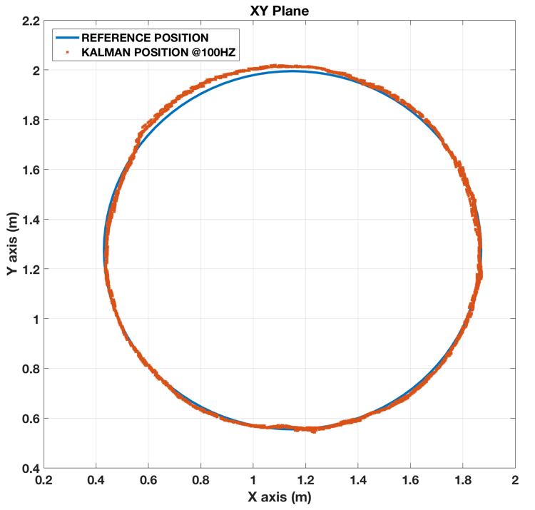
Estimated position and velocity are inputs of position controller. PID position controller is designed, with low pass filter at 15Hz for D-term. The PID controller calculates desired roll/pitch angles from error between input and set point in X-Y plane, and send angle commands to Ardupilot attitude controller in Althold mode. The feedforward controller is added in trajectory flights (circle and infinity) to cancel out centrifugal force (2nd derivative of trajectory position function)
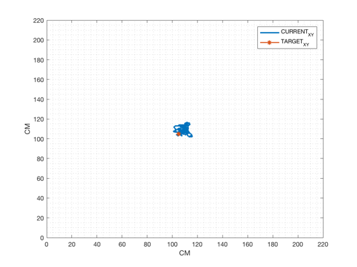
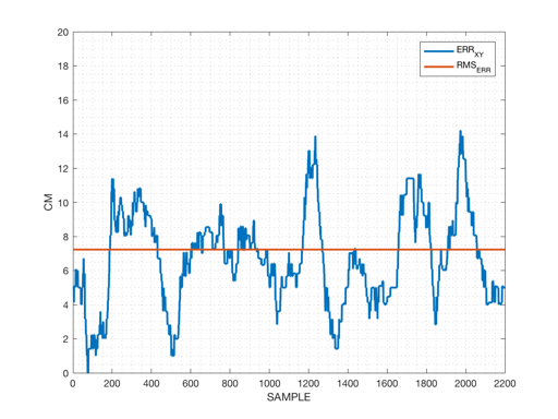
Hover
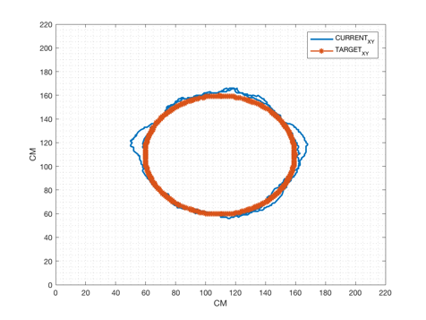
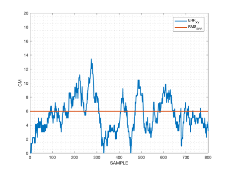
Circle Trajectory
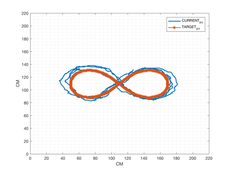
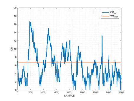
Infinity - Type 1: Lemniscate of Bernoulli
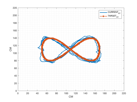
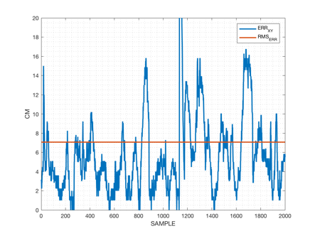
Infinity - Type 2: Lemniscate of Gerono
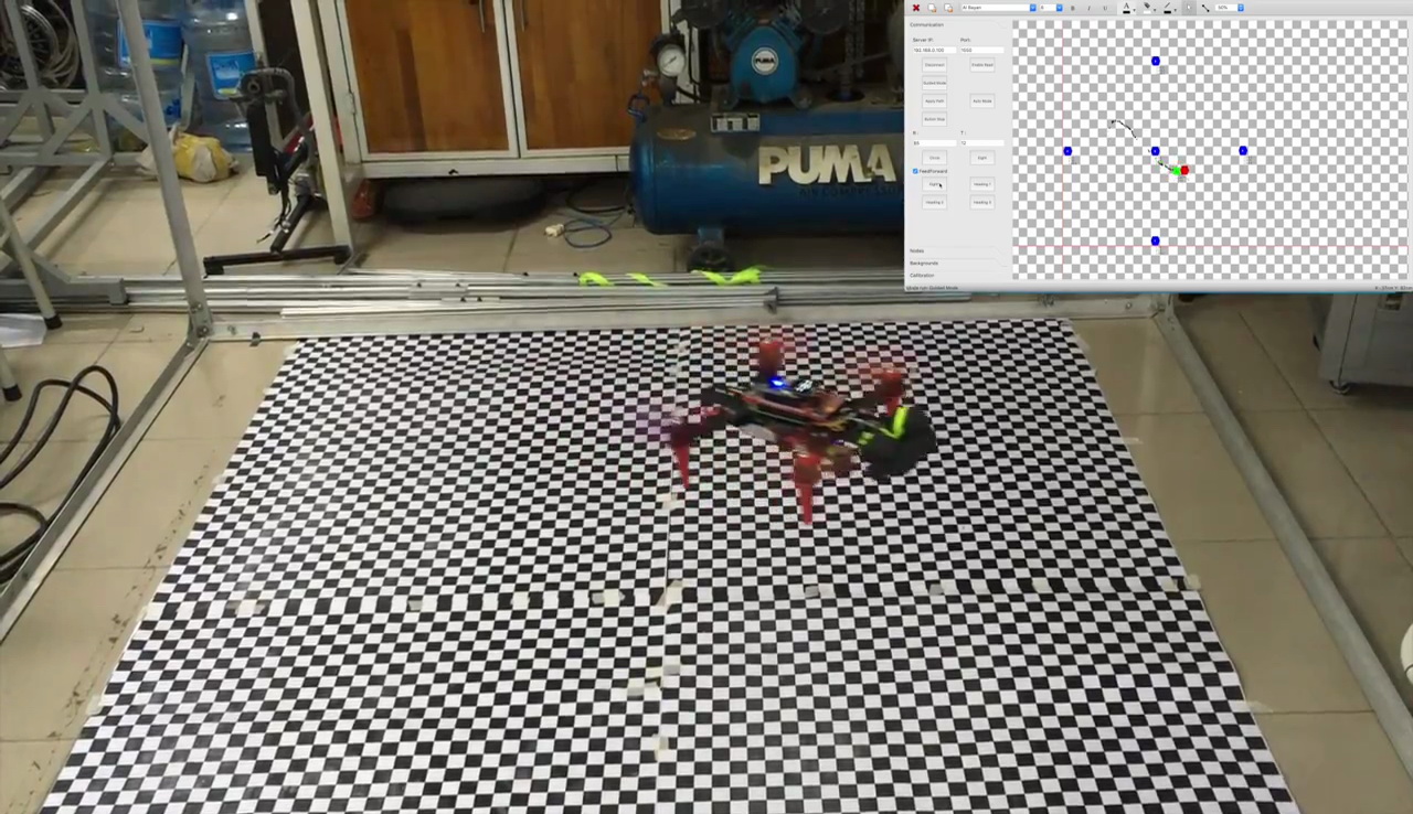
3. Guidance Software
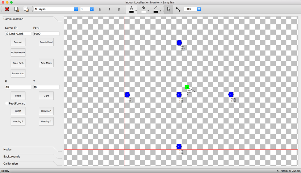
The software is designed with the following functions:
- Show copter position (Green square box) and its heading (Straight line)
- Change between Guided Mode, Auto Mode and Trajectory Mode (watch the video for all flight mode demo)
- Sensor node calibration for indoor localization system