I got my GHkit and had to make a all new cable as the contacts on the GH are different from the DF on the old one. Now I am faced with the Telemetry radio I previously used has the same issues. Cables are not compatible with CubeOrange. What telemetry setup are you using with Orange? I cant find the cheap Holybro that was used a couple years ago with GH cables. I can find the RFD900x only
On my mower, I use the Holybro 915MHz radio set that appears to be out of stock everywhere. It has never let me down.
I use this one from Amazon on my Copter, but it appears to have skyrocketed in price, and the build quality is not the same as the Holybro ones.
I recently found this mRo version that I think I’d trust a little more than the one I linked above on Amazon. mRo makes pretty high quality components.
Regardless of source, you may have to do some soldering or terminal crimping to get the connector style you need. While many of these companies endeavor to make things plug and play, there isn’t always a one-size-fits-all solution.
Rustey, I assume you are not planning to use the built-in WiFi communication on the boards. If you are, there are a few more complex changes you have to make. If you are not using that, you only need to install a jumper in the 40E position (circled in red below), assuming you have the same version of the PCB as I do. I think they may have revised it and I am not sure if anything related to jumpers changed. I have had my board since they were first introduced. Putting a jumper on 40E (and NO jumpers on 10E, 20E and 30E) disconnects the F9P UART1 RX line from the ODIN WiFi module and connects it to the Arduino D connector.
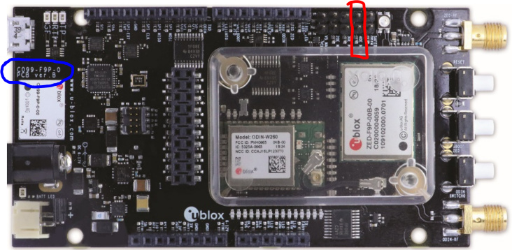
To connect to the a Pixhawk 2.1 (Cube), connect RXD-ZED to GPS1 pin 2 and TXD-ZED to GPS1 pin 3. I’m using an Screw Terminal shield. You can see the white and blue wires from what is labeled as D0 and D1 on the shield to the the GPS1 connector on the Cube. (D0 connects to RXD-ZED and D1 to TXD-ZED no the C099-F9P.)

I’m not sure if you are planning to have both GPSes on the mower so you can have a Moving Base configuration or just what. I’ll be glad to help anyway I can with those connections if you wish. I am running 2 C099-F9P boards on my mower (you can see a bit of the 2nd one at the lower left of the pic above.)
Looking forward to hearing more about your project!
Kenny, Thanks for getting back to me so quick! The pic’s worth a thousand words. I plan to use a moving rover with a fixed base. I do have a later C099-F9P rev. pcb ver E so I’ll have check out the jumpers but I doubt they are different. No I don’t plan to use the on board ODIN module. Plan to use a couple of telemetry radios. tied to my old laptop…base station which I will mount on my wheel chair( a Kubota atv 500) I cannot walk long distances any more. plus I want to be able to chase this thing down In case of catastrophic failure. I’m somewhat out in the country. Not a lot of people around. I learned the hard way that you cannot have enough Fail safes!
I had a typo in my last post age =77 not 67. enjoy your youth!
Best regard’s, Rustey
P.S. want hear more about your sprayer, when you get it started.
1 Like
Sounds great, Rustey! Man, that’s quite a wheel chair! Looking forward to seeing how it all works for you.
@ktrussell Perhaps you can help me with a hint…
I am using GPS yaw on a drone with ArduCopter since several months but until now with relaying the RTCM data between moving base and rover via the Pixhawk Cube Orange. The modules are two ArduSimple SimpleRTK2Blite:
Via Mission Planner I feed RTCMv3 correction data that I get from a fixed base via NTRIP.
During the betas I also went through all these problems with unhealthy GPS etc. and with 4.1.0 beta5 the drone had a crash due to EKF3 position estimation going mad: EKF3 position still going mad in beta5 - drone crashed
Until now it is still not clear what caused this behaviour but one of the countermeasures that I want to take now is to unload the relay traffic through the Pixhawk by directly connecting the two UART2 ports of the ArduSimple modules.
The current documentation simply says
You may instead install a cross-over UART cable between the two UART2 connectors on the two GPS modules. If you do that then you can set GPS_DRV_OPTIONS = 1 which tells the u-blox GPS driver to configure the two GPS modules to send RTCMv2 data over UART2.
Do I understand it right, that only one wire is required? Going from the TX2 port of the moving base to the RX2 port of the rover?
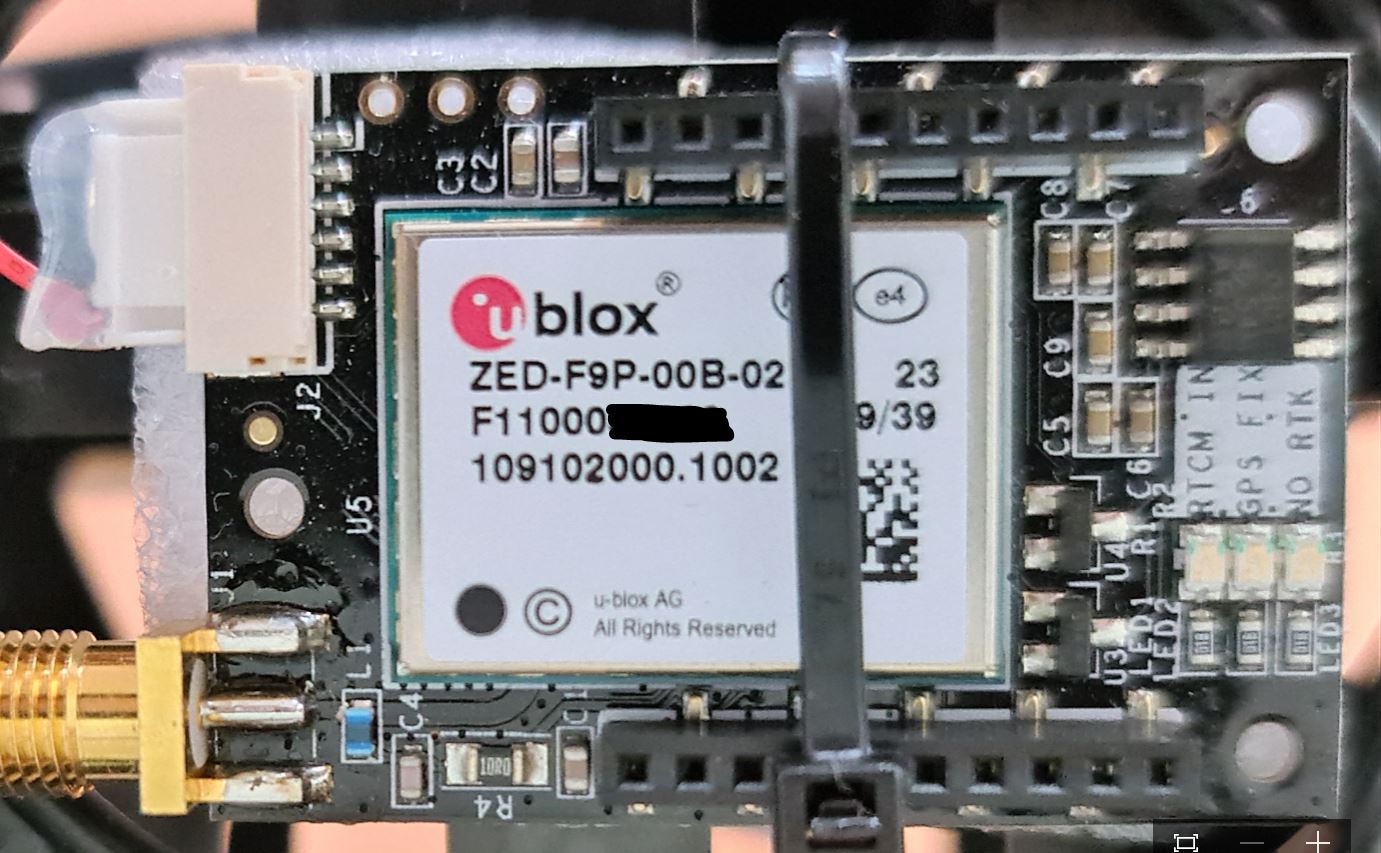
On the modules, I see no marking. As it was mentioned here that RX and TX are mislabeled on the SimpleRTK modules, is this the correct mapping?
UART1:
UART2:
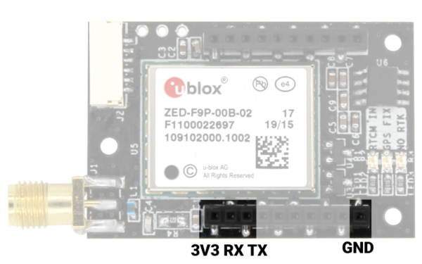
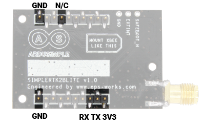
The pictures were taken from the ArduSimple documentation at simpleRTK2Blite hookup guide - ArduSimple
In my opinion this must be wrong - both pictures seem to show the same UART (but one is from the bottom and one is from the top side, connectors going through).
Would it work to piggyback these modules?
Will the moving base still consider the RTK correction data coming from the ground via Mission Planner MAVLink messages?
First, I’m inclined to trust the ArduSimple documentation regarding the pinout. Those look like surface mount headers and sockets (note the solder left or right of each pin), so they probably do not connect through the board. Thus UART1 is exposed on the pin side and UART2 is exposed on the socket side if we are to believe the documentation.
However, the documentation still has the TX/RX labeled in a counterintuitive way. If you look at the XBee pinout, XBee TX (data out) is adjacent to 3v3. As such, the ArduSimple board actually receives data on the socket labeled TX and transmits on the socket labeled RX.
So, connect a wire from the RX-labeled socket of GPS1 to the TX-labeled socket on GPS2 and set GPS_DRV_OPTIONS=1. There will be no effect on UART1/MAVLink RTCM3 injection, and you should get more reliable RTCM3 from the moving base to rover.
You might get away with piggybacking the boards if the rover is the one on top. You’d still set GPS_DRV_OPTIONS=1 to do so.
@Hacky, I think @Yuri_Rage has answered perfectly. It is interesting that you have two SimpleRTK2Blite modules rather than two SimpleRTK2Bs or one of each. As long as both UARTS are exposed somehow on the Lite modules, you certainly should be able to connect them just like the full modules. You just don’t have the slight benefit of using Arduino screw terminal shields 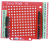 or similar, which I really love for external wiring.
1 Like
Hey Rustey, that Cub Cadet looks ready for action. I have attached my current parameters. If you connect both the Moving Base and Rover GPSes via their UART1 ports to the Cube, you do not have to configure the GPSes. Ardurover will do that for you.
How are you planning to get the RTCM3 corrections from NTRIP into your moving base? Are you going to use Mission Planner with MAVLink Injection? Here are my parameters currently in use:
2021-08-29 4-1-0rc1.param (15.3 KB)
You should only use them for reference, of course, since your servos will not behave just like mine and your GPS antennas and flight controller locations will be different, etc.
If you are using C099-F9Ps, this will help you with which pins to connect to the Cube:
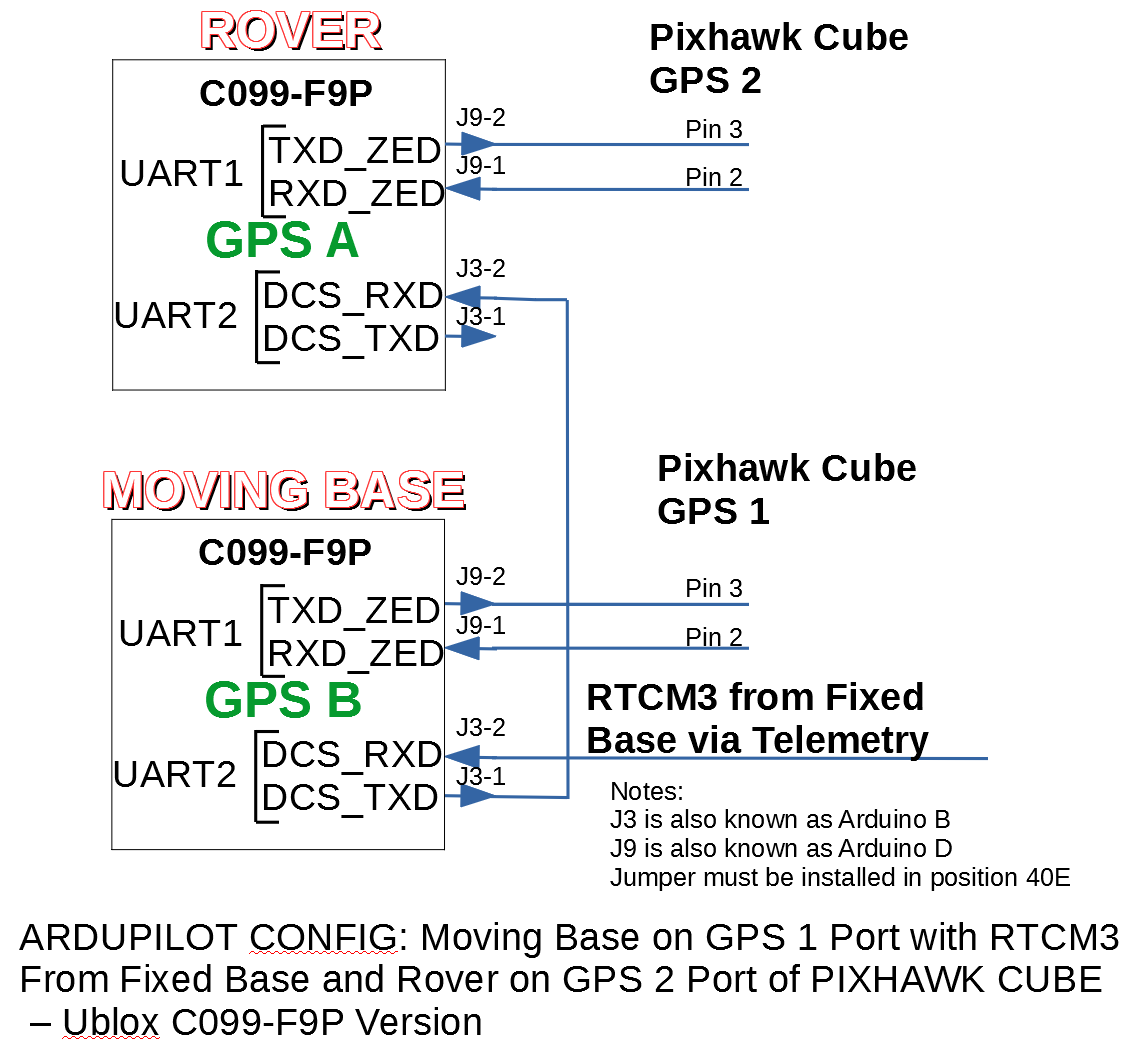
Note that if you are using MAVLink injection, you will not have the connection to J3-2 on the Moving Base. Also, note that you need to put a jumper on position 4OE, and no other positions.
I have issue for ahrs_orientation when use 2 GPS.
Set it’s value to 2, reboot, no any changes for yaw.
Don’t connect any GPS on serial port, it works.
Roll90 works.
Kenny, your parms seem to work “THANKS” But I now have a disarmed that I can’t seem to get rid of .Any suggestions.
Rustey
Not without more details. Does it give you a message as to why it isn’t arming? Do you have a safety switch? If not, be sure you have BRD_SAFETYENABLE set to 0. Read this: Arming / Disarming — Rover documentation (ardupilot.org).
Kenny, do you think i could obtain Gps Heading combining a working pair of c94 and a one Sparkfun ZED-F9R ? I am now using original USA version of c94 set for 868 Mhz and 38400 baud and it just works.I still have a pair of c94 with disabled radio and set to work with the Feather M0 according to your instruction.Would absence of second Uart be a show stopper ?
It sounds like you are headed for frustration, but have a look at how ArduSimple suggests to configure their boards with similar limitations. Also, the Neo-M8Ps may not perform well enough to get you stable yaw/heading results.
1 Like
Kenny, Yuri and I work out the Arming/Disarming issue last week but now have fail safe problem related to error between base and rover. I’m working on mounting the a/p system on my cub cadet too field test the system. Will get back to you on that . Many Thanks to you and Yuri. Rustey
2 Likes
I had never thought about doing GPS for Yaw with C94-M8P, but I see that it does support it, per the documentation for the M8P. So, I assume you could probably make what you suggest work. As Yuri mentioned, however, it will likely be frustrating. You will certainly have to configure all your GPSes manually. If I were going to try this with 2 C94s and 1 F9P (or I guess F9R that you mention - which I have not used), I would probably use the F9P as the moving base so that it can be connected to the Flight Controller as GPS1. Then your Rover C94 would be connected to GPS2. You will have to set GPS_AUTO_CONFIG to 0 and do all the configuration in Ucenter. You will need to be sure the baud rate from the Rover GPS to the Flight controller is at 230400. Since the C94 only has one UART, that will be the baud rate for your Moving Base to Rover GPS also. So, you would not be able to use your 38,400 for your RTCM3 coming in from the Fixed Base to the Moving Base. So, you would likely need to implement some other telemetry (such as the Feather) to get the corrections into the Moving Base. You could, though, I guess use MAVLink injection for the RTCM3 from Mission Planer.
That is a lot, but might be doable.
1 Like
Thanks to you and Yuri it is much clearer what the main challenges are. The requirement for antennas to be the same level as fmu, and the 230400 baud is all a revelation to me  .I knew the main problem will be single UART but i hoped with f9p inbetween i would get away with it.But as i understand now it is not the movig base to get the eventual RTCM from fixed base but the rover. So in this kind of “harness” the rover gets corrections from both the fixed and the moving base via apropriate msg ?
I wil keep trying over the winter and if it does not work ill buy another f9.Thanks
Kenny and Yuri , I mounted my a/p set up on my wheel chair , now being out doors and Hexagon NTRIP corrections I have GPS 2 (rover) with RTK FIXED on HUD . I still have failsafe on HUD . prefight check show telemetry signal 0 and Batt level 0 V. I am using a single pwr supply with multiple voltages to pwr all the boards from a 12V on board Batt. I have no need for the lipo batt. Is there a way to turn off the Batt level message? All the batt parameters (that I can find) are set to 0.
Do you use telemetry 1 to connect to your GS.
No, the Moving Base gets corrections from the Fixed Base. The Rover gets corrections from the Moving Base. That is all. And you do not have to have the GPS antennas at the same level as the fmu. You define an origin (0,0,0) as the center of rotation of your vehicle. You measure the X, Y, and Z distances (as defined here) in meters to each GPS antenna and to the INS (FMU). You insert those measurements in the position parameters for each antenna and the INS. (The specific parameters are shown further down on that same page.)
1 Like