That makes sense for sure, but I could’ve sworn that setting anything other than 10Hz resulted in nearly constant “Unhealthy GPS Signal” warnings, which is why you see the parameters as they are. I have a little more mowing to do this week (hopefully tomorrow), and I will reconfigure with the 5Hz rate.
1 Like
I have my rates at 100mSec also. I did a lot of tuning yesterday. I plan to do more today. I will go back to 200 also, as in the pre-Yaw days and see what happens. I had figured a compass would update much faster and so we needed the GPS Yaw data as fast as possible also, especially for pivot turns. Randy did point out at post 93 above that the EKF blends the gyro and heading info so that a fast update rate is not required but it has been working at 100 so I haven’t touched it. I am using external RTCM3 communication between Moving Base and Rover.
1 Like
@tridge, so far, I am achieving better success with the GPS rates at 10Hz, but it’s not as good as setting them at 5Hz and keeping the uBlox UART2 ports connected. I’m getting more frequent (and valid) Unhealthy GPS Warning errors with the 10Hz rate, where both GPS modules will briefly display “No Fix” and then recover. GPS yaw is definitely useable in this configuration, but it reports 65535 more often than with the following configuration that I have used successfully over the past year or so:
- GPS_DRV_OPTIONS=1
- GPS_RATE_MS=100
- GPS_RATE_MS2=100
Unfortunately, I think I just broke the PTO drive belt on the mower, and the logs I have so far are a bit hard to decipher (I made a lot of parameter changes in short order, rebooting often, and creating many logs in a short period of time).
I will definitely report back soon with more and better info, along with the supporting logs.
Unrelated…to the FIFO testing - @rmackay9, you mentioned previously when I sent an unrelated log that you noticed some noisy steering behavior, so I dug into that a little more - my steering tuning needed some refinement for sure, and that aggressive NAVL1_PERIOD likely needed to be tamed just a tad. I have a much smoother PID curve now, and I think I can do even better! Thank you much for the feedback.
2 Likes
Ok, good news - the belt just came off the pulleys while mowing some high grass. Easy fix!
Unless you object before I have a chance to execute this plan, I’m going to download logs of two nearly identical sessions - one with the autopilot-in-the-loop parameters as described by @tridge, and one with the parameters that have best worked for me thus far (I will leave DMA disabled for both sessions). I’ll send the logs your way as soon as I have them.
1 Like
Logs uploaded per above.
While the mower tracked nicely during both runs of the mission, GPS2_RAW.yaw frequently reported 65535 and both GPS modules showed “No Fix” intermittently throughout the session with the autopilot in the loop at 10Hz, while the UART2 crossover session at 5Hz appeared far more stable.
1 Like
Follow up post on the DMA disabled/FIFO testing - success! 5Hz was the ticket, of course. There were multiple, brief GPS yaw dropouts during the session, and the GPS modules occasionally flickered a “No Fix” status, but the EKF was able to persevere and provide a stable platform with relatively little EKF yaw innovation (discrepancy between predicted and reported GPS yaw). The pull request has already been approved.
Tridge taught me a valuable lesson in .bin log analysis with respect to GPS-for-yaw, which has altered the way I will approach things in the future. While there might be “Unhealthy GPS Signal” warnings at times (or often) and GPS yaw dropouts (65535 reported), it’s critical to review EKF performance rather than one’s own perception - in other words, the mere presence of the warnings doesn’t tell the whole story, even when they appear to be frequent.
So far, I’ve found that an EKF yaw innovation of +/- 3-7° (max) seems to be nominal performance, with most of the values falling within 3°. Plot XKF3[0].IYAW from a .bin log to analyze. It may also prove useful to plot GPS[1].YAW as well as GPS[0].Status, GPS[1].Status, and GPS[1].Yaw to correlate innovation with GPS fix state and reported yaw.
Another important lesson learned is that my recommendation to run the GPS modules at a 10Hz update rate (GPS_RATE_MS=100 and GPS_RATE_MS2=100) is counterintuitively detrimental. With UART2 crossover communication, you can get away with those settings and receive fewer “Unhealthy GPS Signal” warnings because the autopilot will receive position updates faster than the minimum “healthy” rate of 5Hz.
However, the bandwidth available at the faster rate doesn’t support reliable transmission of the full messages, resulting in poorer EKF3 performance. Thus it’s best to set the slower 5Hz rate (GPS_RATE_MS=200 and GPS_RATE_MS2=200) and suffer more GPS warnings to maximize EKF performance.
As I understand, consistent 5Hz messaging is the minimum rate at which the autopilot considers the GPS to be healthy. Therefore, any GPS message glitch/loss will result in “Unhealthy GPS Signal” warnings (a 0 bit is sent in the GPS place of the SYS_STATUS MAVLink message). So it follows that when we are operating right at the threshold rate for GPS health that we will receive more frequent warnings despite improved performance.
With that in mind, I’d humbly suggest either a more robust GPS health determination within the autopilot itself or, failing that, an option to suppress “Unealthy GPS Signal” warnings in the HUD and speech sections of Mission Planner (keeping them present in the message pane only).
4 Likes
I’m using a RYOBI electric zero-turn mower. I’m bypassing the handle controls completely, so no need for servos and mechanical linkages. I send controls from the cubepilot orange through an LC lowpass filter (to convert the PWM to analog voltage) and then straight to the drive computer. I believe your Exmark has a hydraulic drive system, Yuri, so this wouldn’t be useful to you. But if anybody wants more info on my setup, please let me know!
3 Likes
Great analysis and write-up, Yuri, as usual. This knowledge will be very helpful to me, for sure.
For what it’s worth, I ran my mower probably 20 hours over the last 3 days, mostly tuning, but some mowing today. I had both GPS Rates at 10 Hz for about half that time, until I learned from your input from Tridge that 5 Hz was preferable and so the last half was at 5 Hz. I am using direct UART2 to UART2 comm and I NEVER got an “Unhealthy GPS Signal Health” message. I did not monitor the GPS yaw status to see if I ever got a 65535.
Thanks again.
1 Like
The title of this thread is locked, presumably due to the length of time it’s been active, but the it should read: now beta6
I put some serious work into the mower over the past few days, and I think it really paid off.
First, I uploaded a video detailing the wifi enabled fixed base/telemetry station that I’ve been using for most of the project. I’ve hardly touched it in over a year - it just plain works…every time! I know many of you have been asking for more details, and I intend for that video to be the first of several in a series.
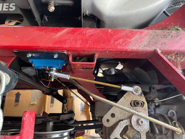
Then, partially motivated by this breakdown, and mostly because there was just too much monkey motion between the steering servo horn and the transaxle (with a ton of stacked washers as makeshift spacers and no good bushings/bearings anywhere), I upgraded the steering linkage and removed nearly all of the free play in the system.
My first attempt failed. I didn’t realize just how close the rear tires are to the frame, and my servo mount interfered with the tire.
So I changed things up a bit and mounted the servos inboard. Thankfully, the Heim joints have enough articulation available to remain free throughout the range of motion.
I was kind of proud of the creative use of fasteners in the pic below. I wanted to solidly locate a 1/4" bolt through the 7/16" hole in the top of the transaxle control plate. It turns out that a #8 washer is a perfect press fit for that hole, so after carefully drilling a few of them out to 1/4", I pressed 3 of them into the hole using a bolt, washer, and nut. It really worked well!

If you’re not interested in clicking the video links, here’s a picture of the linkage I made. It’s only mocked up in this picture. Final install included lock nuts, LocTite, and some zip ties to tidy the wiring.
The resulting linkage requires a slightly shorter throw of the servo arm than previous and achieves full stop-to-stop motion, where the previous version actually couldn’t quite push the control plate to the full forward position. As a result, I had to redo all of the SERVO1* and SERVO3* PWM parameters.
I used the Servo Output page under Setup in Mission Planner to set the end stops by visually observing the PWM value where the plate was at full travel, and then I jacked the mower up and started the engine to roughly set the trim values to neutral (no wheel movement). I then fine tuned the trim values using @ktrussell’s wheel tracking method, where you put a piece of tape on each wheel (still jacked up off the ground), push the RC stick forward in manual mode, and tune the trim values up or down to achieve the same wheel speed on each side.
Since the servo travel is significantly different now, it was necessary to retune the throttle and steering parameters. Because the mower was already pretty well tuned previously , I was able to use a waypoint file and auto mode to do much of the tuning (in a wide open spot). A word to the wise - don’t underestimate the importance of CRUISE_THROTTLE! Set it first and get it right (or undershoot slightly, I think).
Once the throttle was tuned, I moved on to steering. The lack of free play in the system was apparent, and everything was more responsive. I was able to slightly increase the FF gain, and I noticed a probable error in my previous tune with a very high I value, and things calmed down a bit when I backed that off. I then moved on to pivot turn tuning, mostly just messing with ATC_STR_ANG_P in small increments until it nailed the heading on each turn.
When things were looking pretty good, I fine tuned the WP_RADIUS parameter to ensure that the mower pivoted as close to the actual waypoint position as possible. I already have the ATC_ACCEL* and DECEL* parameters about as aggressive as I can make them, so changing WP_RADIUS is the mechanism I used to ensure pinpoint turn precision. I think too small a WP_RADIUS can have ill effects in waypoint nav, so be careful setting it too low (or zero). I ended up at 0.43m.
With the mower turning almost exactly on top of each waypoint, I was able to really dial ATC_STR_ANG_P so that it exits every turn with minimal under/overshoot.
Lastly, I wanted to see how the GPS_POS* and INS_POS* parameters might help or hinder things. When I tuned my quadcopter, I recognized just how precise these flight controllers can be, and how important “perfect” inputs are. The big lumbering mower masks some of the precision available within the flight controller, so I got great results without worrying too much about the exact science of accelerometer or GPS position with respect to turn axis. But now that the steering and speed were pretty dialed in, perhaps there was more to be gained.
I took some careful measurements, referencing the rear (drive) axle centerline, which should be the pivot axis. The GPS antennas were only about 2" aft, but I entered a negative X offset to account for that, nonetheless. The Cube is almost a foot forward of the rear axle, so I entered a positive X offset. Just for grins, I entered a negative Z offset for the GPS antennas as well, since they are nearly 2 feet above the flight controller.
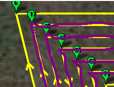
The result was quite interesting! I had to retune the steering parameters slightly, and what minimal overshoots I had became less. In fact, it appears that things are dialed in so closely now, that I can determine that the mower doesn’t do perfect pivot turns. It looks like the outside wheel travels a little farther than the inside wheel, making a little diagonal trace on each turn (pic below). I’m curious to see if I can bias the servo trim a little toward the reverse direction and get even closer to perfect.
EDIT: Alternatively, perhaps I have the GPS_POS*_X a little too far forward with respect to the actual pivot axis. Since it’s easier to change that than to retune the servo output, I’ll try that first and, if that works, bias INS_POS*_X rearward by the same amount. I expect that I’ll have to increase WP_RADIUS by the same value as well to keep things on track.
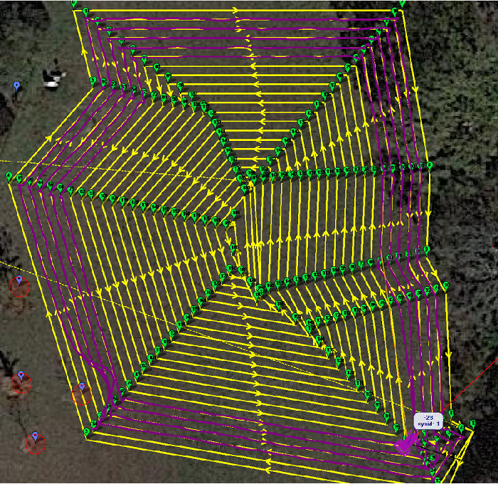
Ok, enough of the diatribe. Results! This is probably the single most perfect mowing pattern I’ve ever achieved, and I’ve gotten some pretty good ones! I ran out of daylight (and solar battery on the fixed base), but for the 6-9 passes I got done, I saw absolutely no skips, even when the mower reversed direction, which is typically the most problematic spot. There’s still just a bit of nav/steering oscillation that looks worse on the MP screen than it does in real life. I’ll report back if I ever solve that entirely.
3 Likes
That is an awesome result from your upgrade and fine-tuning of parameters! I have never looked at the INS_POS parameters. I can’t wait to try working with that myself. I’m curious what scale that mowing pattern is. What is the approximate distance of the very top horizontal path, for example? (yeah, I’m trying to compare my tuning to yours!  )
)
1 Like
Compare away! It’s about 90’ across the top, and the whole pattern is around half an acre.
1 Like
I was afraid you would say something short like that. I have to zoom WAY OUT for my deviations to look that small. Man, that is amazing. Congratulations… AGAIN!
2 Likes
Yes, really great stuff and nice write-up.
Kenny’s “wheel tracking method” for tuning the SERVOx_TRIM values is very interesting to hear about.
… also your method of adjusting the WP_RADIUS so that it stops right on the waypoint is very interesting. I had vaguely thought that getting the balance between WP_RADIUS and ATC_ACCEL/DECEL_MAX right was important for getting good pivot turns (it avoids the sudden position error that results from “reaching” the waypoint) but I have never heard of anyone doing this before (I don’t read everything of course but still, it’s the first I’ve heard of this… TBH, I hope this will become unnecessary once we move to SCurves.
Anyway, great stuff!
2 Likes
Thanks much, Randy! Since you’re here - I just noticed a 4.2.0-dev branch. Will that include SCurves? Should I be gearing more toward 4.2.0, or is it wiser (and/or more useful to you) to continue beta testing 4.1.0 for now?
There’s not much new in the 4.2 yet so I’d stick with the betas for now at least. I have a development branch with SCurves in it but it is half baked and not worthy of testing just yet. Once the dust settles a bit more on 4.1 beta testing (especially for Copter) I hope to get back to SCurves for rover.
1 Like
By the way, Kenny’s method is probably most useful for those of us not using ESCs. We’ve briefly discussed it before, but these “big” machines are driving physical hydrostatic actuators via servos (or linear actuators) that take advantage of the fact that the throttle commands from the FC are easy to translate PWM signals. If you’re using an ESC, it likely becomes much easier to get perfectly matched output on multiple drive motors.
1 Like
I’m sorry I haven’t yet replied to you, @Kevin_OBrien. That sounds like a very cool way to control your mower. While I’m not interested in building one myself, I’d love to see a thread detailing your mower and the drive mechanism you describe.
2 Likes
@Kevin_OBrien I completely glossed over your statement that you are automating an electric zero-turn. I didn’t know they made such a thing. Looks interesting and I second Yuri’s motion to see more info on your setup.
1 Like
I made some interesting observations today while chasing the perfect pivot turn. I think I completely ruled out servo PWM values as the method by which to fine tune the little pivot anomaly shown in my last long post. Rather, the INS/GPS position offsets need to be dialed in correctly to achieve perfect pivot behavior.
I did try PWM tuning to reduce the pivot error and achieved a modicum of success that way…at the complete expense of straight line tracking. It doesn’t appear to be a good method and is likely masking one error with another. It’s likely best to tune the servo min/max/trim values for best straight line tracking and tackle pivot tuning separately.
And then I beat my skull against the wall all afternoon messing with the GPS/INS X offset values. After some careful measuring and re-measuring, I found that the GPS antennas are 2.5" aft of the pivot axis, and the Cube is 10.5" forward. So I set GPS_POS*_X=-0.0635 and INS_POS*_X=0.267, expecting the stars to align and the tune to be perfect.
It got worse. Through hours of trial and error, I finally achieved a good looking pivot turn with GPS_POS*_X=0.35 (WAY forward of the actual physical antenna position) and INS_POS*_X=0.26, which made no sense and worsened the nav tuning. It just made pretty pivot turns.
Then I discovered that if I had the GPS and INS X offsets within 0.1m of one another, the turns looked better than the picture above, no matter what the magnitude of the values - they just had to be within 0.1m, and the turns looked pretty good, which is probably why I was getting such good results with absolutely no X offset at all before.
After some more monkeying around with numbers and trying to make sense of it all, I think I discovered that the best result was achieved with the GPS_POS*_X offset exactly 0.0635m less than (aft of) the INS_POS*_X value. Maybe it’s confirmation bias, or maybe there’s something to it. But I’m seeing nearly perfect pivots with INS_POS*_X=0.27 and GPS_POS*_X=0.2065 (I increased the INS offset a little, and it seemed to tame some oscillation, so perhaps my measurement was off…or perhaps there’s another factor at play here).
I guess it’s possible that the FC first biases all GPS positions by the values of the INS_POS* parameters, and then biases them again by the GPS_POS* parameters, which is the only way I can make sense of what I observed. I have not seen documentation to indicate that, nor have I dug into the code to confirm or reject the theory. Perhaps the EKF innovation values in the logs will help in the process of discovery.
I have a LONG video attempting to share my adventure with all of this - I’ll try and edit it down to something reasonable and record some sort of conclusion when I’m happier with the overall tune (messing with the INS position forces a change in many of the rate parameters). I’ll post it later this week.
EDIT:
Possible firmware issue discussion opened here.
And the related YouTube video
3 Likes
A quick weekend update before I walk away from the mower and computer for a bit to actually socialize with people instead of machines (I may prefer the latter…  )
)
Since the cheap Amazon hardware worked so well, I sprung for some proper tie rods and oil-impregnated Heim joints (McMaster-Carr and I have a love/hate relationship for sure…).
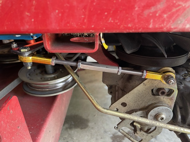
With these, I think I’ll be able to really dial in the straight line tracking, adjusting the rod length for trim position and then working out the min/max values with a handheld tachometer - thanks to @ktrussell for that idea!
3 Likes