Why not just control the motors directly? Leave the manual controls in place, but find some motor controllers capable of driving the motors and devise a way to selectively switch between the two modes of control.
Servos/actuators are necessary evils on hydraulic controls. They will only add induced error on something with electric motors on the wheels.
Hi Bob,
Yes, the override switch method is simple and easy to implement…that’s what I did. I used some optical relays and set them up to be connected to the rotary encoders from the steering levers when powered down (or logic level 0), and to be connected to the output of the flight controller with logic level 1. The mower’s computer takes in a voltage (most likely 0-5V) from the rotary encoders and controls the high-power wheel motor drivers based on this analog signal. I was using an autopilot that only output 3.3 volts, so I had to use a microcontroller to read the analog voltage and scale the output to be 0 to 5V. Another note, your mower will likely trigger a fault for values less than 1 volt, 1 volt to ~2.4volts is reverse (with lower voltages going faster in reverse), 2.4-2.6 volts is motors off, and above 2.6 volts is drive forward with higher voltages mapping to faster speeds. You should jack up the mower so the drive wheels aren’t touching the ground and put a voltmeter on the rotary encoder signals while you move the drive levers…then you can have a complete mapping of your drive voltages since your values might be different than mine.
I definitely recommend staying away from the servos…lots of added complexity that you don’t need to deal with since you have an electric mower!
-Kevin
Thanks for your input. While I think manual use will be relatively rare, I appreciate your feedback about manually moving the servos. That along with an unnecessary stage to add more potential lag and hysteresis, I will pursue either bypassing by providing the motor controller the appropriate input, or supply the motors power directly.
Great suggestion Yuri, but modern brushless DC motors have fairly complex controllers, and ones that work on 56 volts with the amount of current provided for moving this heavy mower could be done, but are expensive and heat producing. I’d rather not replicate this unless I have to. I think replacing the input to the existing onboard motor controllers or the input to their control computer as Kevin has done will likely be the easier path.
Using the 0-5V analog input is a perfect, low cost solution and probably easy to switch between autopilot and manual control with no fear of mixing the two.
My point was to avoid a mechanical linkage if possible.
I was curious how you went about wiring a button to record a waypoint in ardupilot. The docs say
Missions can be created by driving the vehicle around intermittently recording the vehicle’s position as a waypoint by toggling the channel 7 switch.
But if controller is not connected, and the RCIN port is only 3 pins, does it require that I use some sort of signal combiner. (opposite of a breakout board)
Remote Control Receiver System — Connects to a hand-held transmitter that an operator can use to manually fly the vehicle (shown is a PWM receiver with PWM->PPM converter).
So, did you use one of these PWM->PPM converters and attach the button to input number 7?
Perhaps this question should go in a different thread or a new one, but I know that you’re quite active here.
I don’t use any physical buttons on the vehicle for saving waypoints, and I find that to be a strange requirement. However, if that’s what you want, have a look at the BTN*_ parameters and the wiki page about GPIO and button behavior.
I am also trying to use the LR kit to send fixed base corrections to the two ArduSimple boards independently of the FC. Were you able to make this work? Thanks.
You shouldn’t have any issues with that. Follow ArduSimple’s instructions. You may not be able to keep GPS_AUTO_CONFIG enabled, depending on the baud rate supported by the radios.
I have worked several days on this issue of using a ArduSimple LR x-Bee radio mounted on the headers of a Simple RTK2B board to also send RTMC corrections over UART2 to the companion RTK2B board. The second board is supposed to receive the corrections over the UART2 channel on that board via a wire. I have worked on U-Center and carefully configured both boards to the correct protocols and baud rates (all to no avail). The radio will receive the correction signal just fine, transmit it to the F9P chip on the board it is plugged into but it does not distribute out on the UART2 connections of the board. Either GPS will indicate RTK Fixed if the radio is mounted on that GPS board. I just can’t get the correction to both at the same time. So far I am coming to the conclusion that the radio has to be mounted on a USB adapter card and by using the UART pins on that card and wiring it to the UART2 of the moving base. I am also considering buying a better radio pair that gives me this option like the Adafruit Feather M0 LoRa that Kenny used to use (before his mower was burned up). @ktrussell Kenny may know more, but I believe he uses a different radio pair and connects the UART of the radio to UART2 on the moving base. I have been working on this problem for days and so far ArduSimple has also not been able to help me. I am thinking that the little 20mw x-bee radio may not give me the range I need even when i get it figured out. If Kenny or @Yuri_Rage see this post maybe they can shed some light. Another option that sounds crazy would be to buy another Ardusimple LR X-bee radio configured by ArduSimple with the same radio code set inside so it would also receive signals from the same base station. I am leaning more towards a different radio pair, one for the base station and one for the rover. I would welcome any thoughts on this matter.
I have also considered going back to my original RTK2B board along with the RTK Light board stacked on the big board, and then the radio mounted on the small board. I would do this just to get going if I thought it would work, but with this external correction signal and this radio, I not so sure that I wouldn’t end up with the same problem.
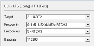
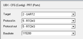
Here are the configurations I put into U-Center. That X-Bee radio uses 115200 baud rate as shipped. and the baud rate has to set at 115,200 on UART2 for even a single GPS board to get an RTK Fix indication. https://drive.google.com/file/d/1EtFTzrvuMF9RD_B4VH89btHwnaCPsDFq/view?usp=sharing
I have’t really gotten my system working yet but I have learned my way around U-Center.
I also know that @jason_miller is interested in also converting over to the external RTCM signal injection so I tagged his name so he can be a part of what ever we figure out.
If I’m reading all of that correctly, you seem to have a fundamental misunderstanding of how RTCM3 and moving baseline configurations work.
The XBee radio is intended to correct the moving base’s GPS position relative to the fixed base such that your moving base position is accurate relative to actual geographic coordinates (assuming a well surveyed fixed base position). In simple terms, this gives GPS1 an RTK fix.
The moving base GPS provides RTCM3 to the rover GPS such that the rover GPS is precise relative to the moving base’s position. That is how we get GPS heading (yaw). You DO NOT need a fixed base for this to work. Again, in simple terms, this gives GPS2 an RTK fix.
If you are getting an RTK fixed status from the GPS upon which the radio resides, then your GPS module settings are probably correct.
To get corrections from the moving base to the rover via a wired connection, connect the moving base’s pin labeled RX2 to the rover’s pin labeled TX2 (yes, that sounds backwards…ArduSimple has a weird pin labeling convention that I’ve grown to hate). Set GPS_DRV_OPTIONS=1.
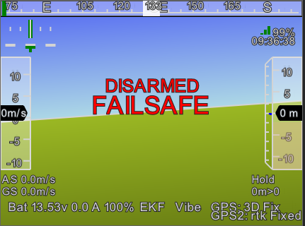
Thanks very much Yuri for your explanation. I did not understand this correctly. I think my GPS1 unit reads GPS fix and GPS2 reads RTK Fix on Mission Planner. Is that what they should be reading?
Well I checked all my GPS_POS* parameters and measured the spacing between the antennas with a tape measure. The antennas were physically setting at 64.7 cm apart and the parameters were set at 66.04 cm only a delta of 1.27 cm. Anyway, I corrected that difference and rebooted the flight controller. Nothing has changed and I get the same GPS: 3D Fix and GPS2:rtk Fixed. I also temporarily disconnected the wire going between the 2 boards and that didn’t change anything either. AlI the messages all stay the same.
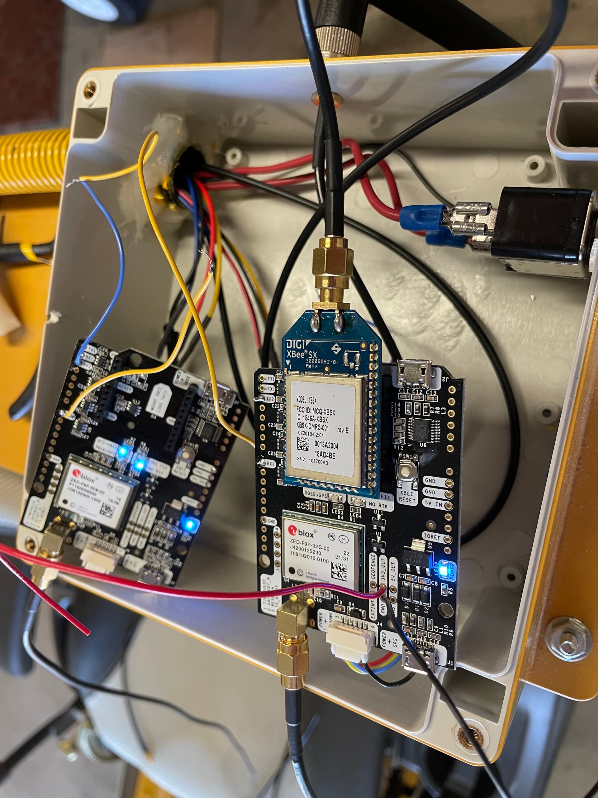
Here is my test setup:
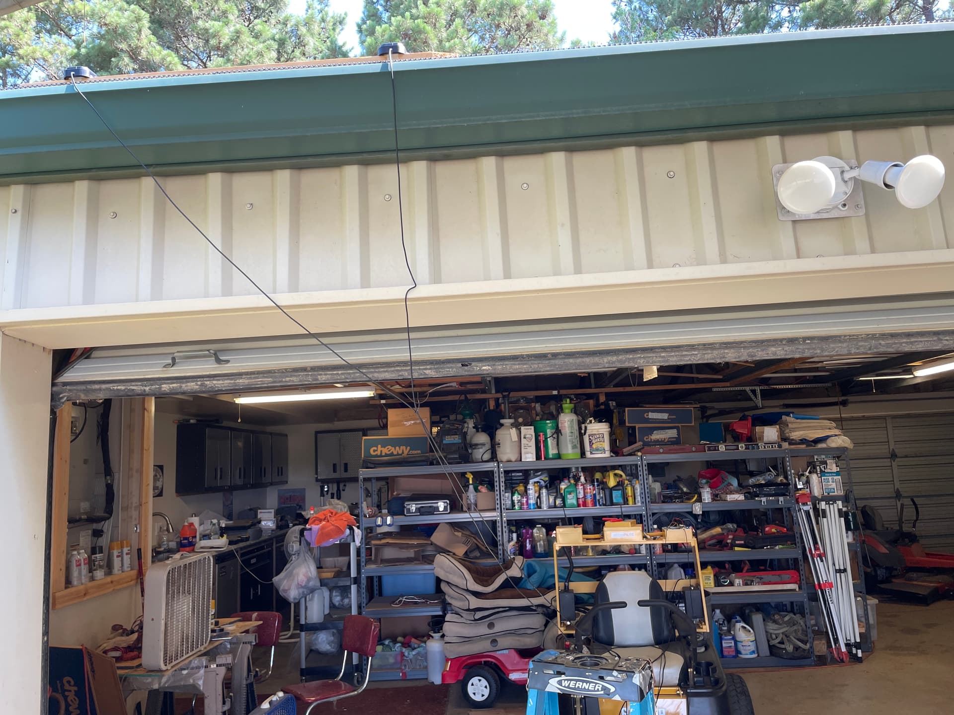
You can see the 2 GPS boards and the moving base has the radio plugged into it. You can also see the connecting wire between the UART2 ports. The antennas are mounted to a board at the correct spacing and moved out the door and sitting on the rain gutter facing up. I throw this in there in case I am causing a problem by how I am testing this.I am still suspicious of the communication between the boards since removing the wire didn’t change anything. I am worried about the radio taking over the UART2 port on that board or some communication protocol not being correct.