During what sections of that log are you flying? Typically on the ground, heli’s do have a lot more vibration. I’m guessing that you were flying from lines 205K to 220K and 270K to 300K. if I guessed correctly then the Z axis is your biggest concern.
As far as lead weight, it depends on how you have the controller mounted. I think most of the examples in that wiki show older controllers that don’t have an isolated IMU. With the older controllers, they are mounted on foam pads. the lead weight was taped to the bottom of the controller to give it more mass and change the vibration absorption characteristics with the foam pads.
where and how have you mounted your controller on your heli?
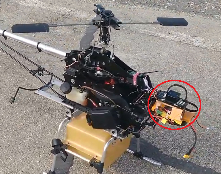
@danielhellin that is not a very good place to mount it. What is supporting it? is there a thin tray that is holding it? I suspect that is the source of your vertical vibration. Some rules about mounting your controller. First try to mount it as close to the Center of Gravity of the aircraft and second, be sure to mount it to the metal/carbon fiber frame. A plastic tray way out on the nose of the heli is not ideal. I have mounted mine sideways to the vertical frame plates. You might want to mount it on the opposite side of the engine cylinder head.
Also where is your GPS? It looks like you have something below your controller, sitting on a battery. The GPS needs to have a clear view of the sky. Most mount it on the tailboom or back behind the rotor shaft.
@bnsgeyer ,
Yes, I know it’s a bad position, but I wasn’t able to find another place. The lower deposit is for fumigation and during the operation it wets everything a lot. In electric helicopters I like to put it under the main axis, at least X and Y coincide with the center of gravity.
If I understood correctly, you put it on a side plate of the chassis turned 90 degrees, is that correct? Then the top is pointed left or right. I have never mounted a flight controller like this, I suppose that once the accelerometers and the compass are calibrated there will be no problem.
Yes, I have made the support with plastic printing, which although it is quite thick,and it is solid fixed to another plastic tray that supports a LiPo.
So, your recommendation is not to isolate from vibrations, it is to change the location, is it correct?
I’ll tell you what, guys. Mounting on the side of the frame with a piston engine is a bad place to be. Works on electrics. But you have to deal with the back and forth accelerations of a single-cylinder piston engine. Every time the cylinder fires the piston accelerates one direction, the crankcase accelerates the other direction.
The rotating mass in the crank counterweights and flywheel has to match reciprocating mass in the piston and rod. And this is another story. I run balanced 2mm stroker engines that have been dynamically balanced to run at 11,500 rpm vibration-free. Besides a 2mm stroker crank, they have lightened piston and rod, and due to the stroke they have higher compression ratio than a stock engine so they can’t run 87 octane pump gas. You can’t achieve secondary (non-sinusoidal) balance with a single-cylinder engine, so it only has a narrow rpm range where it is designed to run.
Running stock engines will always be problematic because the RC-format engines were designed for racing buggies, not helicopters. They have to rebuilt as a helicopter engine, new out-of-the-box.
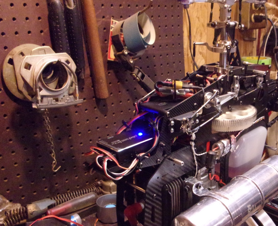
I have my flight control in one helicopter mounted in pretty much the same location as shown in this thread, with zero problems with vibration. It is mounted right directly above the engine’s cylinder and has flown over 80 hours that way - with the cowling on it which encloses everything pretty tightly. Although there is some air ducting designed into the cowling for engine cooling:
Well, your mod it’s really a fine tuning work on engine. And sure, it is only way to minimize vibrations. I will suggest this tunning to the owner of the helicopter.
Just out of curiosity I will try how the vibrations change with an anti-vibration bed and with a change of location
@danielhellin you may be able to isolate the source of the vibration through the batch logging feature. Set INS_LOG_BAT_MASK to 1 and INS_LOG_BAT_OPT to 0. Then you can send me the log and we can look at the relative magnitude of vibrations and make a better decision on which location works better. You could also do it yourself using the vibration wiki
Without optimizing the engine for a helicopter it will be a vibrator. Stuff will come loose on it despite loctite, it won’t handle decent. Sometimes you find a “sweet spot” with stock engines in a reasonable rpm range where you want to run the headspeed, but it’s not very common. Hardly anybody flies a gasser (for very long) with a stock out-of-the-box engine.
Zenoah kept bolting on bigger cylinder and piston since the G240 to get more displacement and power. They all use the same crank. As they added weight to the recip assy with the piston they got worse and worse for vibration. Add to that the factory runout tolerance on the crank is +/-.003". At least pull the crank out of it and put it on centers on the lathe with a dial indicator. Beat on it with a brass hammer until you get it +/- .0005" runout. They use a pressed-together crank, it’s just like truing a Harley crank.
While you got it apart remove 14.5 grams from the piston to lighten it so it matches the weight of a G240 piston. There’s other things you can do but those two items will reduce the vibration by 90%.