I’m glad to hear that there is someone else interested in this. I agree that it should be possible with the dual antenna unit. However, it is somehow expensive and I tried to realize the heading with two standard GPS receivers as we use them all the time. I did some investigation here and can confirm that it is almost impossible if you cannot read the phase information of the receivers and as long as you do not have a huge copter. The only solution in the low cost sector seems to be with the help of RTK GPS.
Please tell me if you have any ideas or progress in that topic.
1 Like
At this stage the cost of two M8P modules and antennas is around $250USD so until they come down in price that’s about the lowest cost of hardware.
Depending on the size of your vehicle the accuracy of the heading is limited to around 0.2degrees/distance between antennas(m). So it may be more appropriate for larger vehicles.
It will be necessary to use rtk on both M8P to maximise accuracy.
The calculation is detailed in the linked document.
We just need to find out how to inject the new yaw value into the EKF.
1 Like
I am very interest in this possible feature. I have a Reach RS+ as a RTK base station and a Reach M+ for the rover. I am willing to get a second M+ if I can get ardupilot to calculate yaw from the two receivers. I have been looking at dual GNSS receiver modules but they are more expensive than the sum of their parts. My project is driving fairly well, but I think GPS based YAW would make a world of difference, I hope. ArduPilot Mower
PS: This is the module I have yet to find a reasonable source for https://www.vectornav.com/products/vn-300
1 Like
I’m also interested in this feature.
I had a chance to use my rover with a NEO-M8N and wheel encoders, and just for kicks I unplugged the compasses and disabled the one internal to the Pixhawk. No EKF errors (I was using EKF3 with the wheel encoders) and once the rover figured out the heading it was rock solid.
At the beginning of the mission, the rover would head in seemingly random direction for a few feet, but after that it figured out its heading and went to waypoints pretty flawlessly. My only complaint was that at the end of each mission it would “forget” it’s last heading, even if the robot was stationary until the next mission, and take off in a seemingly random direction, correcting itself after a few feet.
Food for thought.
1 Like
I’ve been looking through the code to see where the output of the magnetic compass is used. It seems that the mag.field from the compass is used to tilt compensate the heading value. Other than that I’m not sure where the compass actually comes into play for a rover. Is there some other place it acts?
Note that ardusimple is claiming a heading solution using 2 GPS receivers. They are claiming about 0.5 degrees heading accuracy at 1 meter spacing of antennas. https://www.ardusimple.com/simplertk2blite/ Their claims seem supported by this chart on page 5 of the uBlox ZED-FP9 data sheet here https://www.u-blox.com/sites/default/files/ZED-F9P_DataSheet_(UBX-17051259).pdf
I ordered one so will see how it goes. If I can eliminate my magnetic compass on my rover (and switch to a gps based heading) then I can get rid of the 4’ pole sticking out the top - whose sole purpose is to hold the compass up and away from the EM interference from other onboard electronics. (more discussion of that topic here )
1 Like
I’ve currently modified the code to calculate a heading from the differential position between GPS1 and GPS2. Both of which are UBLOX F9P with RTK corrections over 4G running into a custom PCB that distributes the NTRIP corrections to the respective modules. The yaw value is heading and the yaw_accuracy for EKF3 is calculated as the arctangent of the GPS1_HDOP+GPS2_HDOP/distance between the antenna.
It works extremely well. The heading is absolutely locked in. I haven’t seen more than 0.5degree of fluctuation when the rover is stationary. I have the antenna about 1.5m-2m apart, as I’m still testing.
3 Likes
Good luck with your work. It is truly exciting. I cant wait to have this or similar code on my hunk of metal rover.
That’s very impressive @Reuben_Finch, if you get a chance, I’d be interested to see how a shorter distance between antennas performs. The U-Blox link above implies an error of 0.8 degrees with a distance of 25cm between antennas. These F9P modules are performing well beyond my expectations.
1 Like
I’m not running the system as a moving baseline. Both units are being brought into the flight controller and as normal GPS units, though I have modified the ublox library in Ardurover to parse the HPPOSLLH message. I did is this way so that in the future other GPS modules will be able to be used for heading.
2 Likes
But this is an other approach, isn’t it? As far as I know, the rover can determine it’s heading by movement from the change of GPS position. It works great for rover but not for copter as I’m working on the latter one.
1 Like
This sounds great. Is the 4G correction necessary? I think it should also work without and only from the difference between GPS1 and GPS2. Did you try that?
@Christopher_Milner I have two ArduSimple boards. Until now, they are not that precise but I will keep trying.
1 Like
I need the accuracy of the navigation, that’s why I’m using RTK corrections.
1 Like
No corrections are necessary to get accurate bearings between two receivers. Within 40km 2 GNSS receivers will have almost the exact same error. This is how cm accurate baselines are determined but you do not need corrections for this to work.
If you have carrier phase receivers accuracy at 50 cm will be about 2 deg 17 min,
accuracy at 1 meter accuracy will be about 1 deg 9 minutes,
accuracy at 2 meters about 0 deg 34 min.
1 Like
Have you verified this experimentally? How do you ensure that the two modules are calculating their position off the same satellites?
It seems to me there could potentially be quite a variation without the ability to synchronise which satellites are being used for the calculation.
Yes & No I have not other than looking at post processed data. I will rig up a test this week.
set 3 baselines for comparison CA, carrier phase & RTK GPS receivers.
Possibly if you were using 1GPS only & 1 Glonass only or had interference at only one GPS.
Like I said I run a test for ya.
I did run a test today. This does work. If you set up 2 gps just watch as the positions float together. With all corrections off max variations were +/- 6 cm (in 2 out of 20 comparisons). As you suspected, this occurred when one had 16 sv’s one had 17 sv’s. However for most (18 out of 20 comparisons) they were right on +/- 2cm.
For this test the units were 1 meter apart and ran for 1.5 hours. I started recording data after 5 minutes of position reporting.
1 Like
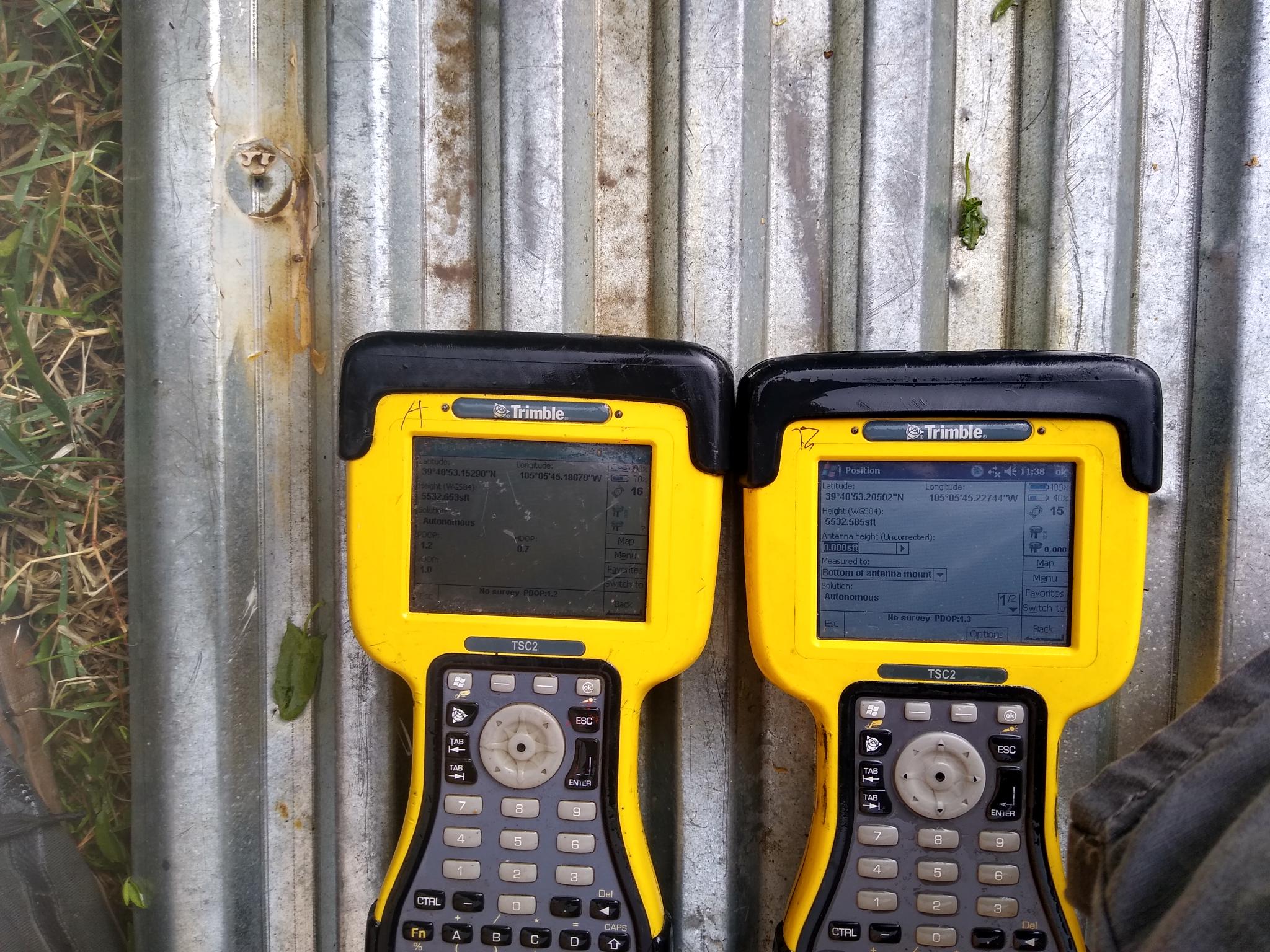

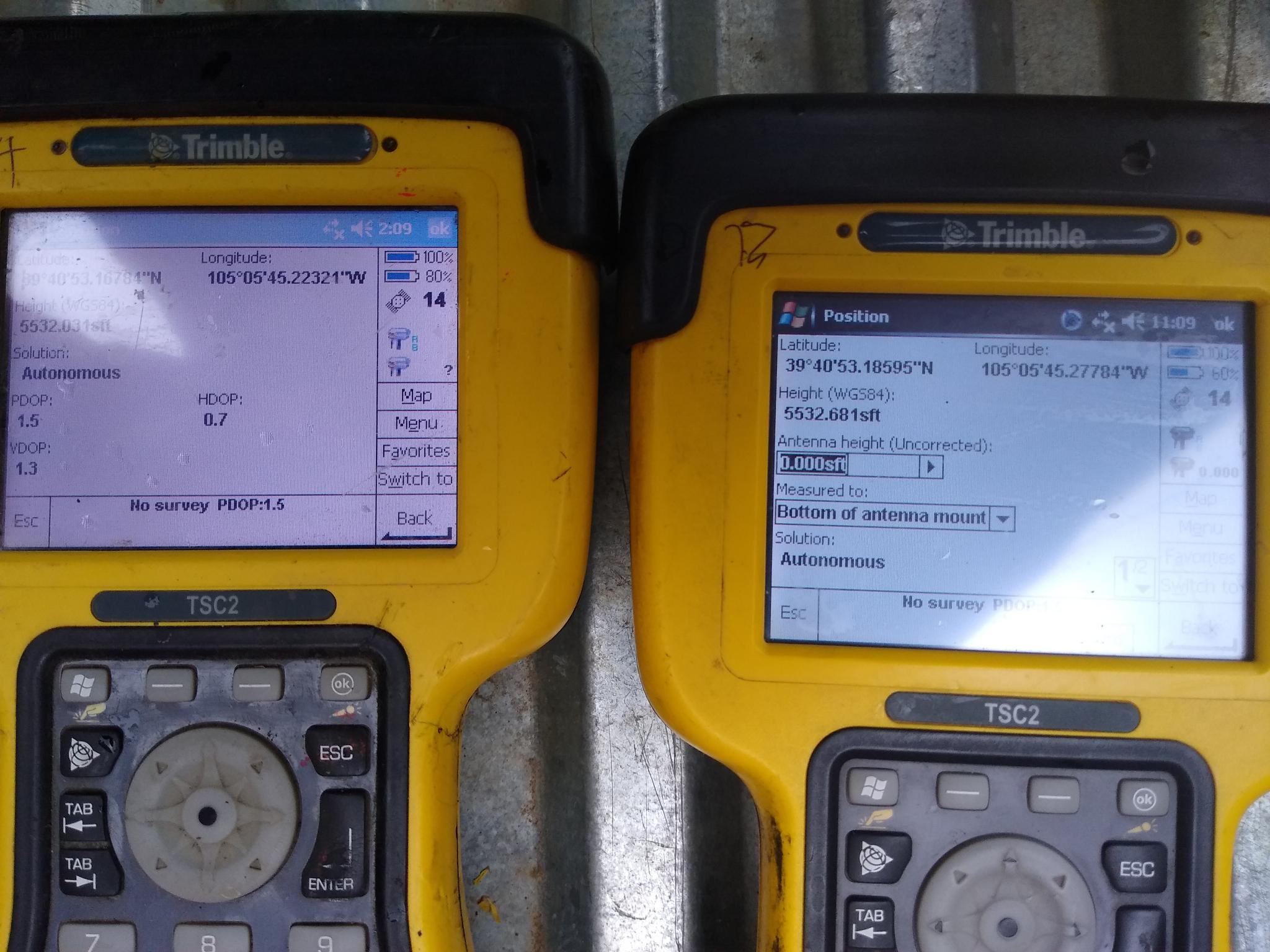
Here are some photos of a 2nd test situation. The 3rd observation you can see a 4.5 degree vertical error when different sv’s are used . The horizontal is much better still.
The receivers are 1.515 meters apart (field measured)
1 Like
Thanks, for this test. We ran a similar test with an Ardusimple RTK. The problem is that it is far from the accuracy of a compass if you don’t have a huge vehicle. I have a copter on a F550 frame which does not even allow me to mount the GPS 1m apart.
Agreed! I do not think Dual GPS is applicable to RC anything. There are some nice compass out now that look like a much easier solution https://store.drotek.com/sensors