I’m attempting to generate a PPM stream via microcontroller to the Pixhawk RCIN port. I’m currently using the Teensy 3.6 and the PulsePosition library.
I’m using the LoopBack example sketch provided in the library examples for this testing. I can generate a PPM stream via the Teensy, confirmed by reading it back on a different pin. I can also read in a PPM stream from a Futaba trainer port. However, I am unable to detect an RC input on the Pixhawk when I send a PPM stream from the Teensy to the Pixhawk. I suspected it could be a logic level issue since the Teensy 3.6 operates at a 3.3V logic level and the Pixhawk is 5V. I used a logic level converter from SparkFun but still was unable to read the PPM signal.
Does anybody have experience using this hardware/library combination for sending PPM to Pixhawk? Could it be a signal inversion issue? I can put it on an o-scope tomorrow and see what the waveform looks like coming from the Teensy.
I’m doing this as a benchmark test as the end result will be to send PPM from the Teensy through the PPM pass through on the RFD900x.
Backstory, I’m using a microcontroller to generate a PPM stream to control different autonomous functions on a rover (auto, hold, arm/disarm, etc) based on input from external sensors. Example: switch from auto to hold when the rover drives through a beam break sensor, switch from hold to auto to resume mission when a different beam break sensor is tripped. Attempting to take a human out of the loop for complex mission operations. I’m just emulating the RC transmitter functionality that would have been controlled by a person, except through a microncontroller with external sensors.
I’m using the LoopBack example sketch included with the PulsePosition library. Instead of hooking the output back to the input to read it, I hooked the output to the Pixhawk RCIN. I also changed the values to be between 1100 and 1900 microseconds.
Upon further reading, it looks like the RFD900x works at 3.3V logic level so maybe I should just try it through the radios and see what happens. Would be strange if it worked through the radio PPM pass through and not directly to the Pixhawk.
Code tested:
#include <PulsePosition.h>

PulsePositionInput ppmIN;
PulsePositionOutput ppmOUT;

void setup() {
  ppmIN.begin(9);
  ppmOUT.begin(10);
  ppmOUT.write(1, 1250);
  ppmOUT.write(2, 1350);
  ppmOUT.write(3, 1450);
  ppmOUT.write(4, 1550);
  ppmOUT.write(5, 1100);
  ppmOUT.write(6, 1100);
  ppmOUT.write(7, 1900);
  ppmOUT.write(8, 1900);
}

int count = 0;

void loop() {

  int i, num;

  num = ppmIN.available();
  if (num > 0) {
    count = count + 1;
    Serial.print(count);
    Serial.print(" :  ");
    for (i = 1; i <= num; i++) {
      float val = ppmIN.read(i);
      Serial.print(val);
      Serial.print("  ");
    }
    Serial.println();
  }

}
@chris.sallis The teensy library is outputting ill formed signal , seems the interframe is not standard.
EDIT: Looking deeper I found the problems
A) You need to generate on falling signal
PulsePositionInput ppmIN(FALLING);
PulsePositionOutput ppmOUT(FALLING);
B) You have to change the TX_PULSE_ WIDTH from 100 to 300 nanosecs at line 66 in PulsePosition.cpp
// The length of all transmitted pulses. This must be longer than the worst
// case interrupt latency, which depends on how long any other library may
// disable interrupts. This must also be no more than half TX_MINIMUM_SIGNAL.
// Most libraries disable interrupts for no more than a few microseconds.
// The OneWire library is a notable exception, so this may need to be lengthened
// if a library that imposes unusual interrupt latency is in use. #define TX_PULSE_WIDTH 300.0
I hope this thread isn’t to old to resurrect, but I’m trying to do the exact same thing as @chris.sallis and am also running into issues. In my case, I’m making a switching device which reads the inputs from multiple DragonLink V2 receivers, selects the one with the best signal strength, and then passes that PPM signal on to a PixHawk. I can read the PPM input just fine, and I can see that it’s trying to send out pulses of the correct width. However, the PixHawk registers nothing. I implemented the changes to the frame rates suggested by @ppoirier but to no avail. At this point, I’m thinking it could be one of a couple of things, but any input is welcome.
Like was mentioned previously, the Teensy 3.2 I’m using operates on 3.3v logic, but the pixhawk reads 5v logic. Further internet research has not given me any clear indication as to whether or not this would prevent it from working.
My PPM signal wire from the Teensy to the PixHawk is not grounded. Is this necessary?
Thanks for your response. Unfortunately, it still isn’t working. I’m posting my code below, if there’s any other suggestions you can offer they would be greatly appreciated. #include <PulsePosition.h> //Include the PPM signal reader/generator library
//Defining Variables

//Input of Analog RSSI Values
#define analogPinOne  A0 // Analog RSSI input from Rx 1
int rssiOne = 0; // value of RSSI from RX 1

#define analogPinTwo  A1 // Analog RSSI input from Rx 2
int rssiTwo = 0; // value of RSSI from RX 2

#define analogPinThree  A2 // Analog RSSI input from Rx 3
int rssiThree = 0; // value of RSSI from RX 3

//Rx PPM Signal Input/Output

PulsePositionInput rxInput1;
PulsePositionInput rxInput2;
PulsePositionInput rxInput3;
PulsePositionOutput pxOutput(FALLING);

//+++++++++++++++++++++++++++++++++++++++++++++++++++++++++++++++++++++++++++++++++++++++++++++++

void setup() {
Serial.begin(9600); // setup serial communication
pinMode(13, OUTPUT);       // LED
pxOutput.begin(23); //initialise PPM output to pixhawk
rxInput1.begin(20); //initialise each of the PPM inputs
rxInput2.begin(21);
rxInput3.begin(22);
}
//+++++++++++++++++++++++++++++++++++++++++++++++++++++++++++++++++++++++++++++++++++++++++++++++

void loop() {

digitalWrite(13, HIGH);   // LED on

//Part 1: Reading and Comparing Analog RSSI Inputs

rssiOne = analogRead(analogPinOne); // read the analog RSSI value from pin A0; Rx 1
rssiTwo = analogRead(analogPinTwo); // read the analog RSSI value from pin A1; Rx 2
rssiThree = analogRead(analogPinThree); // read the analog RSSI value from pin A2; Rx 3

Serial.print("RSSI Values");
Serial.println();
Serial.print(rssiOne);
Serial.println();
Serial.print(rssiTwo);
Serial.println();
Serial.print(rssiThree);
Serial.println();

int rssiValues[]= {rssiOne, rssiTwo, rssiThree};
int maxIndex = 0;
int maxValue = 0;

 for (int i = 0; i <= 2; i++) {
    if (rssiValues[i]>= maxValue) {
      maxIndex= i; //loop through the array of RSSI values to find which one matches the value of the maximum value, giving the index of the maximum value
      maxValue = rssiValues[i];
  }
 }

Serial.print("Max Index ");
Serial.print(maxIndex);
Serial.println();

//Part 2: Forwarding Digital I/O Signals

Serial.print("Available Channels");
Serial.println();
Serial.print(rxInput1.available());
Serial.println();
Serial.print(rxInput2.available());
Serial.println();
Serial.print(rxInput3.available());
Serial.println();

Serial.print("MS Values");

float values[7];

for (int chan=1; chan<=6 ; chan++) { //number of channels received
  switch (maxIndex){
    case 0:
      values[chan] = rxInput1.read(chan); //read the data coming in from the Rx input on channel c
      break;
    case 1:
      values[chan] = rxInput2.read(chan);
      break;
    case 2:
      values[chan] = rxInput3.read(chan);
      break;
  }
  Serial.print(values[chan]);
  Serial.println();
}

Serial.print("Transmitted Data");
Serial.println();

int testValues[]= {1500, 1500, 1500, 1500, 1500, 1500};

for (int i = 0; i <= 5; i++){
  int c= i+1;
  pxOutput.write (c,testValues[i]);
  Serial.print(c);
  Serial.println();
  Serial.print(testValues[i]);
  Serial.println();
  delay(50);
}

Serial.println();
This may be way too old to bring back up, but following in case any new insights (similar issues as @ciarang)
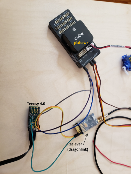
pic of setup: – dragonlink, teensy, and pixhawk all connected w/ ground, voltage, and signal wires
void setup() {
DLRXinput.begin(6); //signal from DL must be connected to pin 6
PXHKoutput.begin(10); //signal to Pxhwk must be coming from pin 10
Serial.print(“Setup Complete\n”);
}
void loop() {
// read in the PWM channels from the DL
int chAil = DLRXinput.read(1);
int chElev = DLRXinput.read(2);
int chThr = DLRXinput.read(3);
int chRudd = DLRXinput.read(4);
Can you confirm that you made this change in the Teensy library?
Are you sending 8ch PPM or something else?
It’s been a while, but I’m pretty sure I have tested this with both 3.3V and 5V versions of Teensy with no modification to the code or library once I had it working, so it shouldn’t be a PPM logic level issue.
Yes I confirmed that I had made that change to the Teensy library and the teensy code was referring to the correct library, etc. I also updated TX_MINIMUM_SIGNAL to 600 from 300 (it recommended it be double the pulse width)
Currently I am sending a PPM with only one channel to test it - I can update that to more channels if that would help it run smoothly. Ultimately I would like to transmit 12 channels on 1 PPM signal.
My mind was somewhere else when I was asking about number of PPM channels. That would be more related to the inability to read rather than write.
The update to TX_MINIMUM_SIGNAL might be something you want to keep in your back pocket until things are working. I don’t recall changing this.
I’ll dig up a copy of my latest working PPM read/write sketch and post it for you to try. It may be this weekend before I get that to you.
If you have an extra teensy, you can hook the PPM output of Teensy #1 to the input to Teensy #2 to verify that an output signal is being generated from Teensy #1. This would narrow the focus to being more Pixhawk related than Teensy.
My memory generally fails me, but I’m not entirely sure I ever tested a direct connection from the Teensy to the Pixhawk with the teensy generating the PPM. My focus was the need to get it working when interfaced with a RFD900x telemetry radio. Theoretically, nothing should be different between those configurations (the RFD900x still had its’ PPM output going to the Pixhawk), but it probably wouldn’t hurt for me to confirm that it works this was as well.
I really appreciate the help. I can change the TX_MINIMUM_SIGNAL back and see if that is necessary or not.
I don’t have another Teensy, but I do have an Arduino Mega that I have put a PPM decoder on and the PPM signal transmits perfectly from the Teensy to the Mega. (it is more difficult to code an encoder, so I have not pursued that option to troubleshoot).
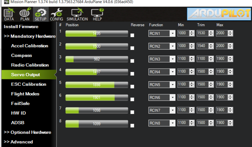
I have been testing the Pixhawk by connecting it to Mission Planner (MP) and monitoring the servo outputs as I change inputs on the TX. With the RX signal wired directly into RCin on the Pixhawk, the servo outputs change as I change TX inputs. However, when I wire the Teensy outputs to the Pixhawk, the servo outputs show no change. So I think there’s some issue in the pixhawk understanding how the Teensy is sending out the PPM?
Not sure if that’s insightful at all, but I really appreciate the help! Your code may be useful to look at.
Pic of MP Servo Ouputs: [nothing is connected in pic]